Assembling the Nearer keyboard
- Table of contents
- Glamour shots
- Introduction
- Quick links
- Designing the layout
- Switches & caps
- Microcontroller
- Designing the switchplate
- Designing the wiring matrix
- Building the firmware
- Arrival of the switchplate
- Hot glue crimes against humanity
- Wiring
- The base
- Stabilizers
- Conclusion
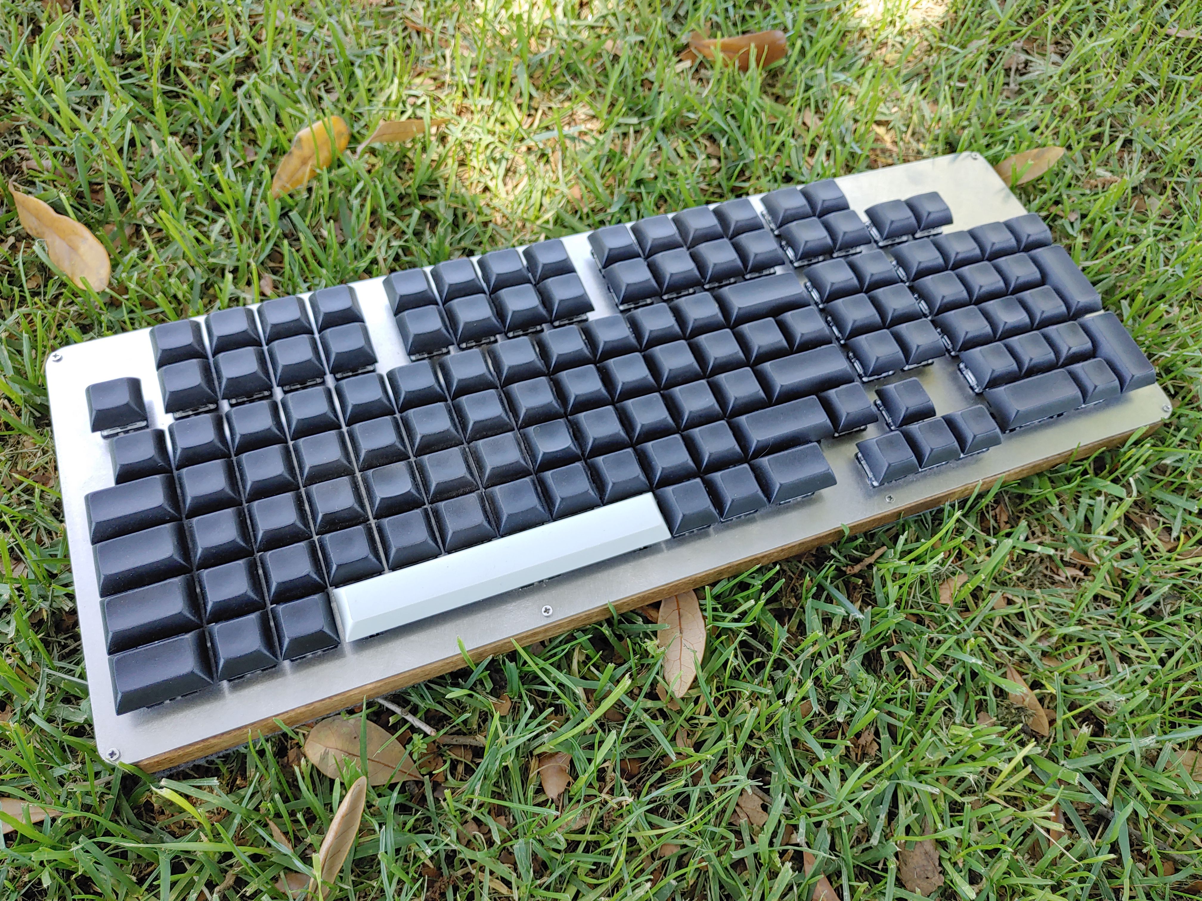
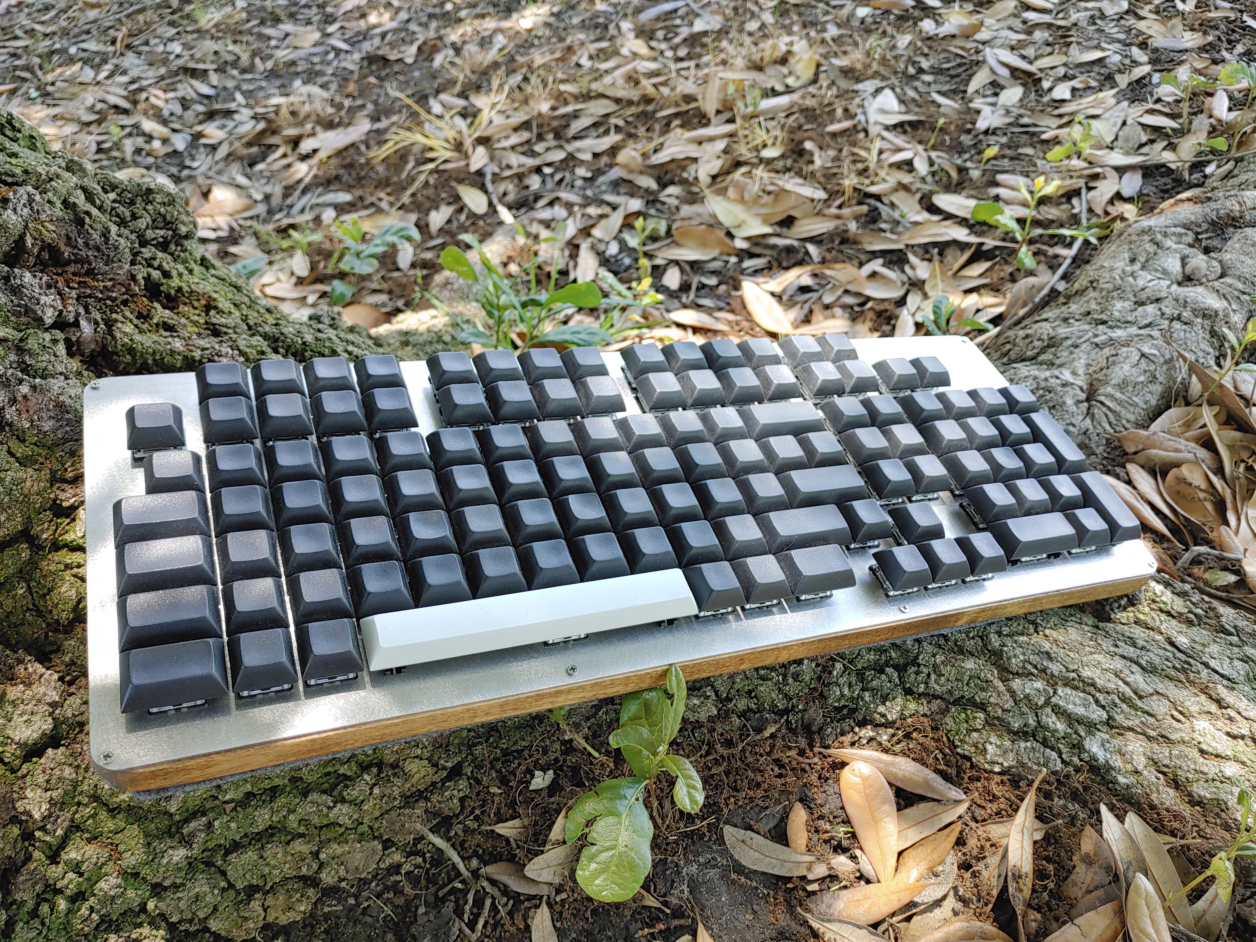
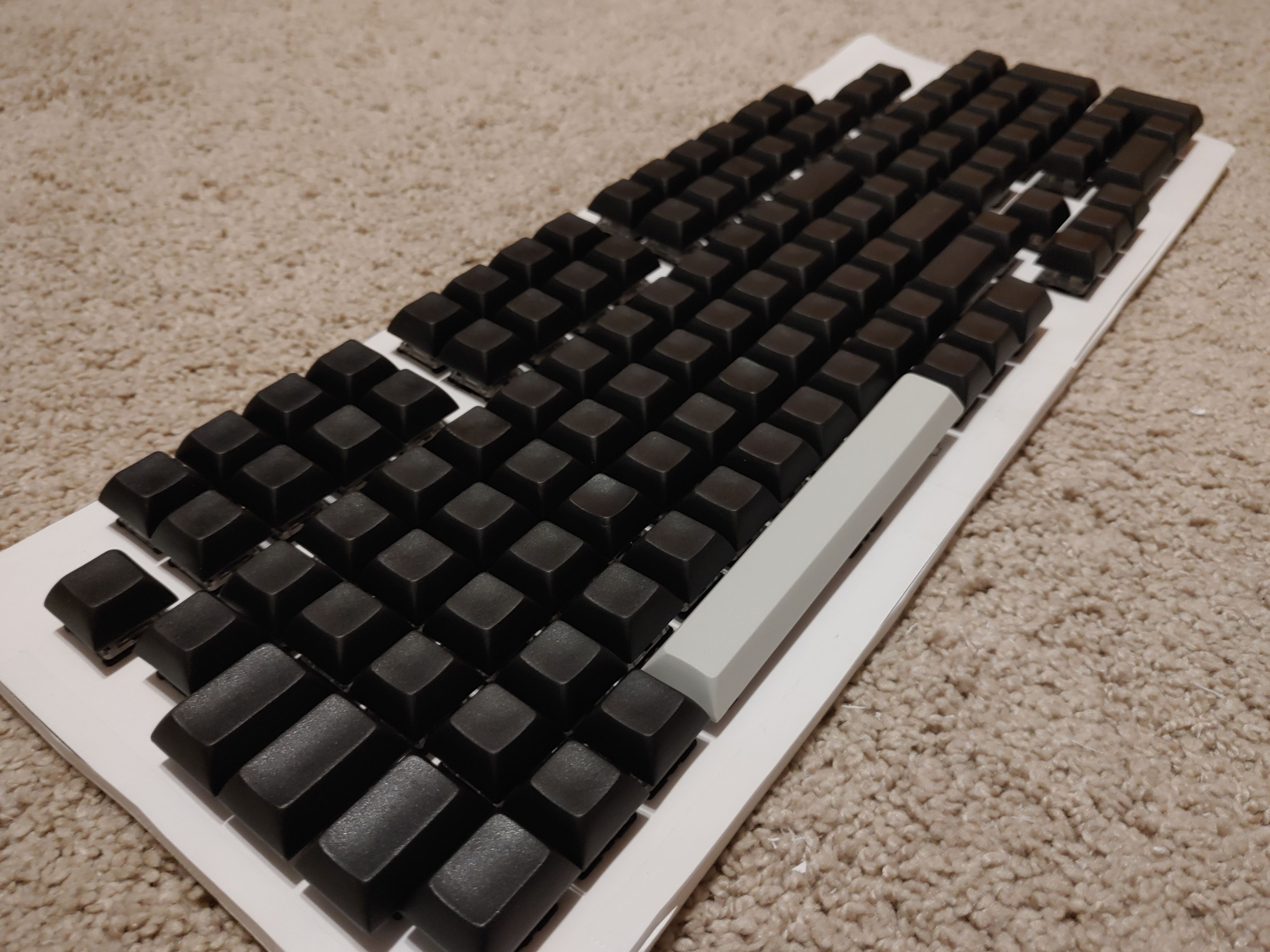
Glamour shots (§)
Introduction (§)
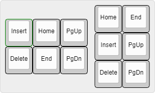
I've wanted a mechanical keyboard for a long time, but have never been happy with the options available to purchase. The main reason, as trivial as it will sound, is that I prefer the Home/End block of keys to be arranged vertically. The standard arrangement is horizontal, and I've never seen a mechanical keyboard with the vertical arrangement.
This alone was enough to get me interested in building my own keyboard, but I put it off for a long time because I knew it would be expensive. Finally, I've gotten around to it. The solution to price anxiety is to start buying some of the parts before calculating the total cost of the project so that you can tell yourself "Well, I can't stop now!".
The result is not perfect, but it's nearer.
I find myself leaning towards the word "assembling" rather than "building" for this project. I have been continuously amazed at how much work the keyboard community has put into the resources and tooling that make assembling a keyboard honestly very easy. Everyone has coordinated around the keyboard-layout-editor data format which makes the transition between each tool at each step of the process totally seamless. Really, I feel like I didn't do a whole lot except for the soldering. But we'll get to that in a bit.
The only actual hard part is making the choices — switch type, plate material, base material, layout, keycaps. You'll see people talk about the sound, feel, and resonance of each part, but it's hard to tell the difference on their videos.
This article will be a mixture of build log, diary, and tutorial. It's a bit long-winded and over-detailed, but that's because I have a new keyboard I need to break in so I want to type a lot. Maybe you'll find something here that other build logs omit. I hope it is useful to somebody.
Quick links (§)
- http://www.keyboard-layout-editor.com (github)
- http://builder.swillkb.com (github)
- https://kbfirmware.com (github)
- https://github.com/qmk/qmk_toolbox/releases
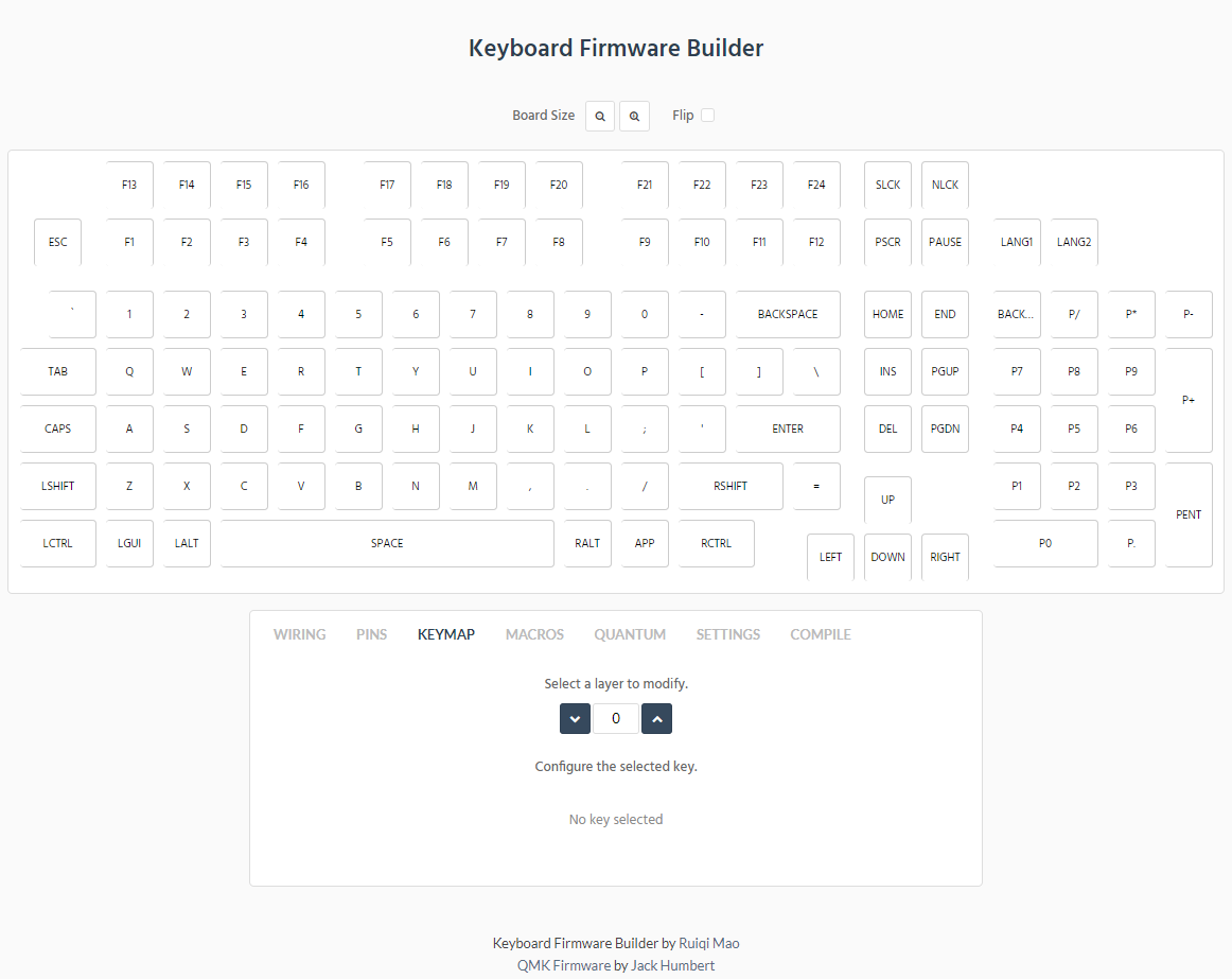
Designing the layout (§)
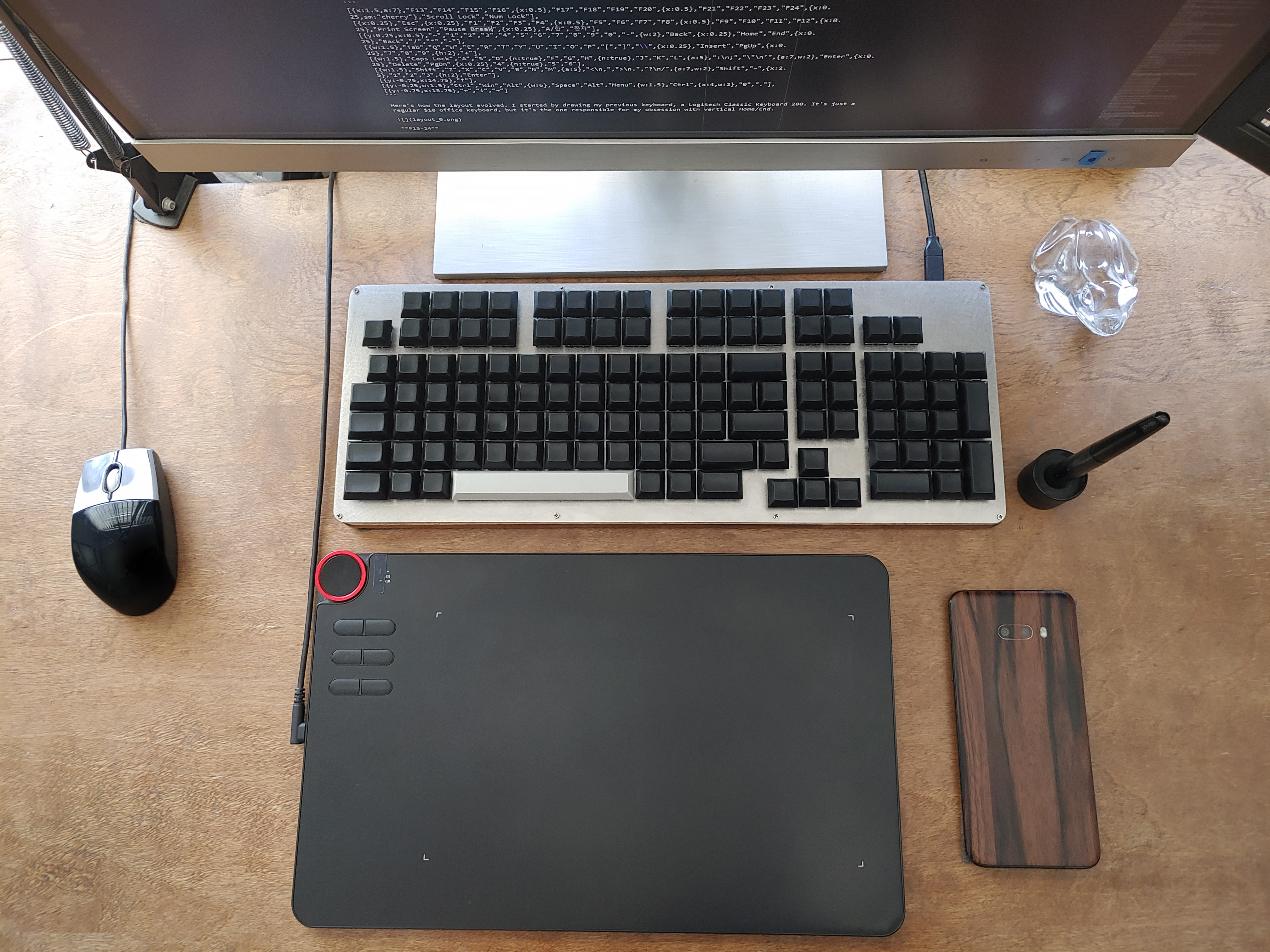
The layout was designed with keyboard-layout-editor.com.
This is the final layout of Nearer:
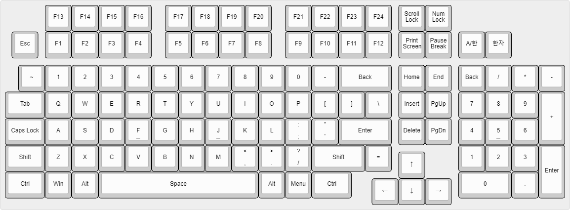
[{x:1.5,a:7},"F13","F14","F15","F16",{x:0.5},"F17","F18","F19","F20",{x:0.5},"F21","F22","F23","F24",{x:0.25,sm:"cherry"},"Scroll Lock","Num Lock"],
[{x:0.25},"Esc",{x:0.25},"F1","F2","F3","F4",{x:0.5},"F5","F6","F7","F8",{x:0.5},"F9","F10","F11","F12",{x:0.25},"Print Screen","Pause Break",{x:0.25},"A/한","한자"],
[{y:0.25,x:0.5},"~","1","2","3","4","5","6","7","8","9","0","-",{w:2},"Back",{x:0.25},"Home","End",{x:0.25},"Back","/","*","-"],
[{w:1.5},"Tab","Q","W","E","R","T","Y","U","I","O","P","[","]","\\",{x:0.25},"Insert","PgUp",{x:0.25},"7","8","9",{h:2},"+"],
[{w:1.5},"Caps Lock","A","S","D",{n:true},"F","G","H",{n:true},"J","K","L",{a:5},":\n;","\"\n'",{a:7,w:2},"Enter",{x:0.25},"Delete","PgDn",{x:0.25},"4",{n:true},"5","6"],
[{w:1.5},"Shift","Z","X","C","V","B","N","M",{a:5},"<\n,",">\n.","?\n/",{a:7,w:2},"Shift","=",{x:2.5},"1","2","3",{h:2},"Enter"],
[{y:-0.75,x:14.75},"↑"],
[{y:-0.25,w:1.5},"Ctrl","Win","Alt",{w:6},"Space","Alt","Menu",{w:1.5},"Ctrl",{x:4,w:2},"0","."],
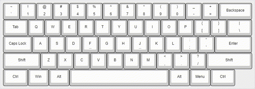
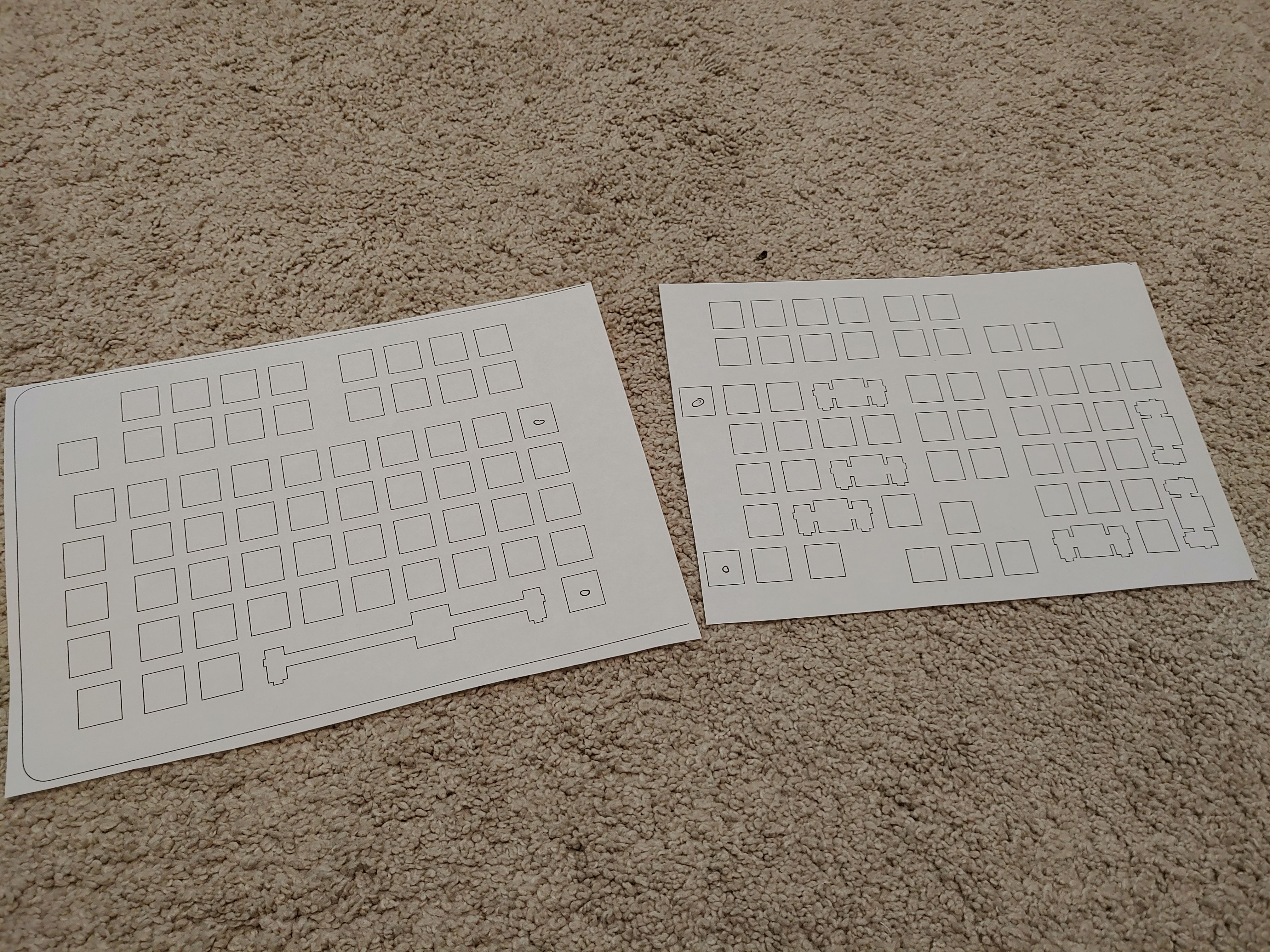
[{y:-0.75,x:13.75},"←","↓","→"]Here's how the layout evolved. I started by drawing my previous keyboard, a Logitech Classic Keyboard 200. It's just a regular $10 office keyboard, but it's the one responsible for my obsession with vertical Home/End.
F13-24
The whole reason I started this project was so that I could have my vertical home/end block, but I felt I should come up with some more customization ideas to justify the time and money. Well... I wouldn't mind having a dozen more F keys to bind, so let's go with that.
Ortholinear
I wasn't originally interested in ortholinear keyboards, but I saw this video by Ben Vallack and was convinced to try it out. Watching this video is like watching the mask come off a Scooby Doo villain. It would be one thing if the traditional QWERTY stagger matched the natural curvature of the hands or something, but the stagger leans in the same direction for both hands. There's just no excuse. So while I'm not ready to commit to a true ergo layout with staggered columns or split halves, I'm willing to make the ortho switch. I'll admit, despite all the time I've spent typing, I'm still really bad at reliably hitting numbers on the number row. Ortho should make that easier once I know that 4 and 7 are above F and J.
KP-Backspace
I always hate when I'm reaching for End or numpad-slash and accidentally hit Num Lock, so I knew from the beginning I'd be moving Num Lock and putting a backspace in its place. That meant putting Num Lock up with Scroll Lock, which makes for a nice 2×2 arrangement. The best part is that Print Screen and Pause/Break are the only ones I plan on pressing regularly [1], so it's nice to not have Scroll Lock in between them.
A/한
I gave myself a dedicated English/한글 toggle key so I could stop relying on my Alt+Menu AHK script. The AHK solution works perfectly fine, but I would occasionally blunder the Menu keypress and be left navigating the toolbar of the current application thanks to the Alt press. I put it next to Right Shift because why is that key so long in the first place.

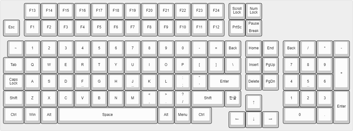
Shift-equals
I was having a hard time fitting the Equals button between Minus and Backspace without reducing Backspace to 1u or taking 1 and Q out of alignment, which I wasn't willing to do. I decided to put it next to shift, and while I knew it would take some time to get used to, it's not unreasonable. That's right, I'd rather break my muscle memory on the equals key than on the home/end block. That's how dedicated I am.
This meant moving A/한 above the numpad. The downside is that this is a much farther reach, but the upside is I have plenty of room up there for a 한자 key too, which I wouldn't have included otherwise. Realistically, I could just map Ctrl+A한 to 한자, so if I ever come up with another need for that key that's what I'll do. You know, after I use up all 24 F keys.
Although I liked the idea of the 1.25u Ctrl giving the left edge of the board a sort of curvature, I found during prototyping that pressing hotkeys is much easier with a 1.5u Ctrl because I tend to strike the leftmost edge of the Ctrl key, especially now that A and Z are physically closer to the left edge of the board — the hand posture for Ctrl+Z is much tighter on this layout compared to the original.
Speaking of hand posture, let's compare the ortholinear layout with the traditional stagger more closely:
![]()
By far the biggest letter changes are on the Z row, with each key moving 0.5u to the left. You can see how much Ctrl hotkeys have changed now that the 0.75u horizontal gap is completely gone. For the first few weeks of using this keyboard, I was constantly overshooting my copy-pastes.
The Q row feels almost identical, and I'm happy to report that the 1u backslash is not giving me any trouble. The number row is almost a full 1u farther to the right now, which is mostly not a problem since I don't feel like I ever really internalized the old stagger anyway. However, underscore did give me a hard time since it's almost a full 1u to the right from where it used to be, and now neighbors backspace. Equal has definitely taken some getting used to, but I've got the muscle memory for it now.
[1] Pause is used to pause commandline applications, and Ctrl+Break is used to kill commandline applications that aren't terminating on Ctrl+C.
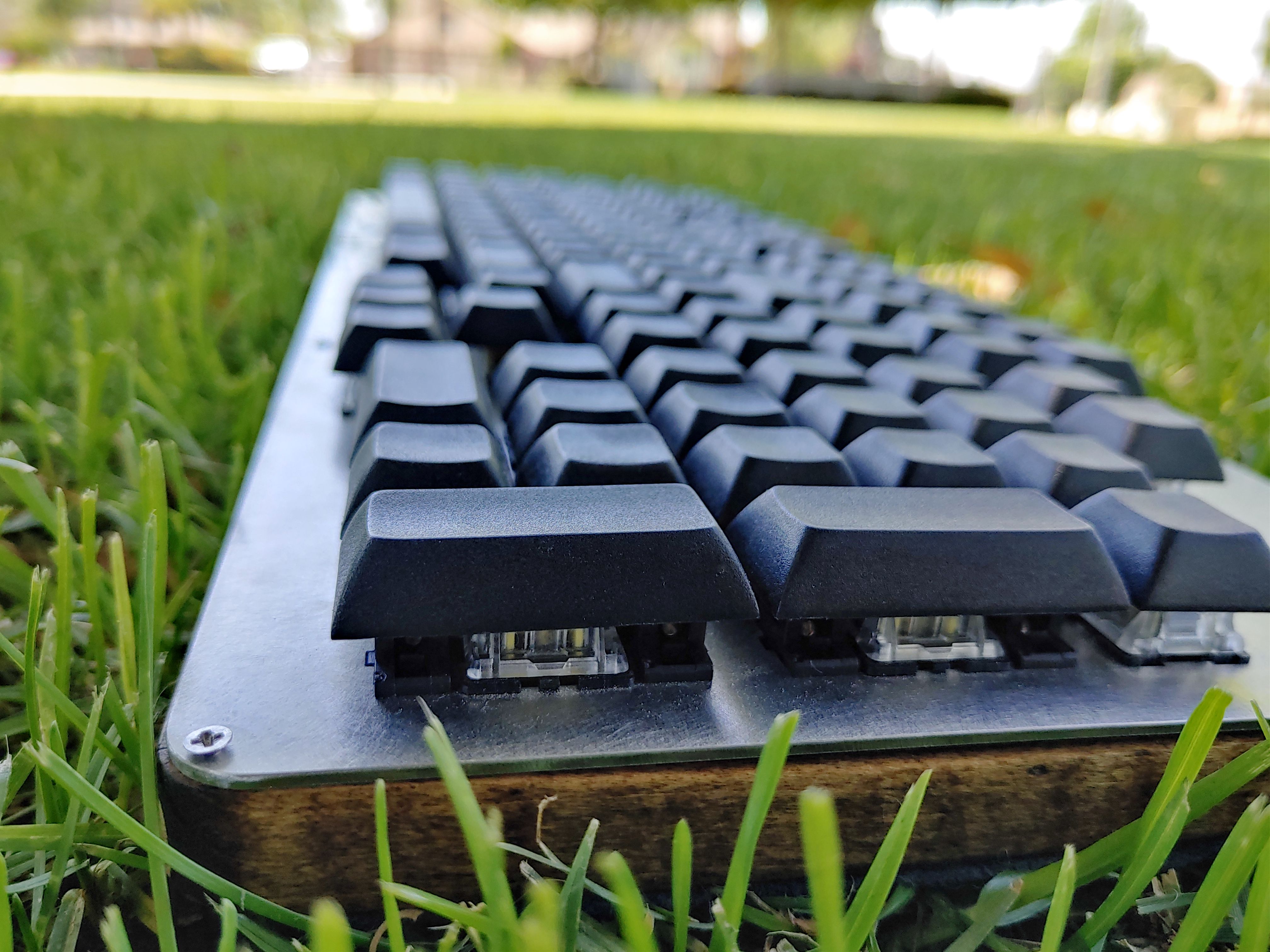
Switches & caps (§)
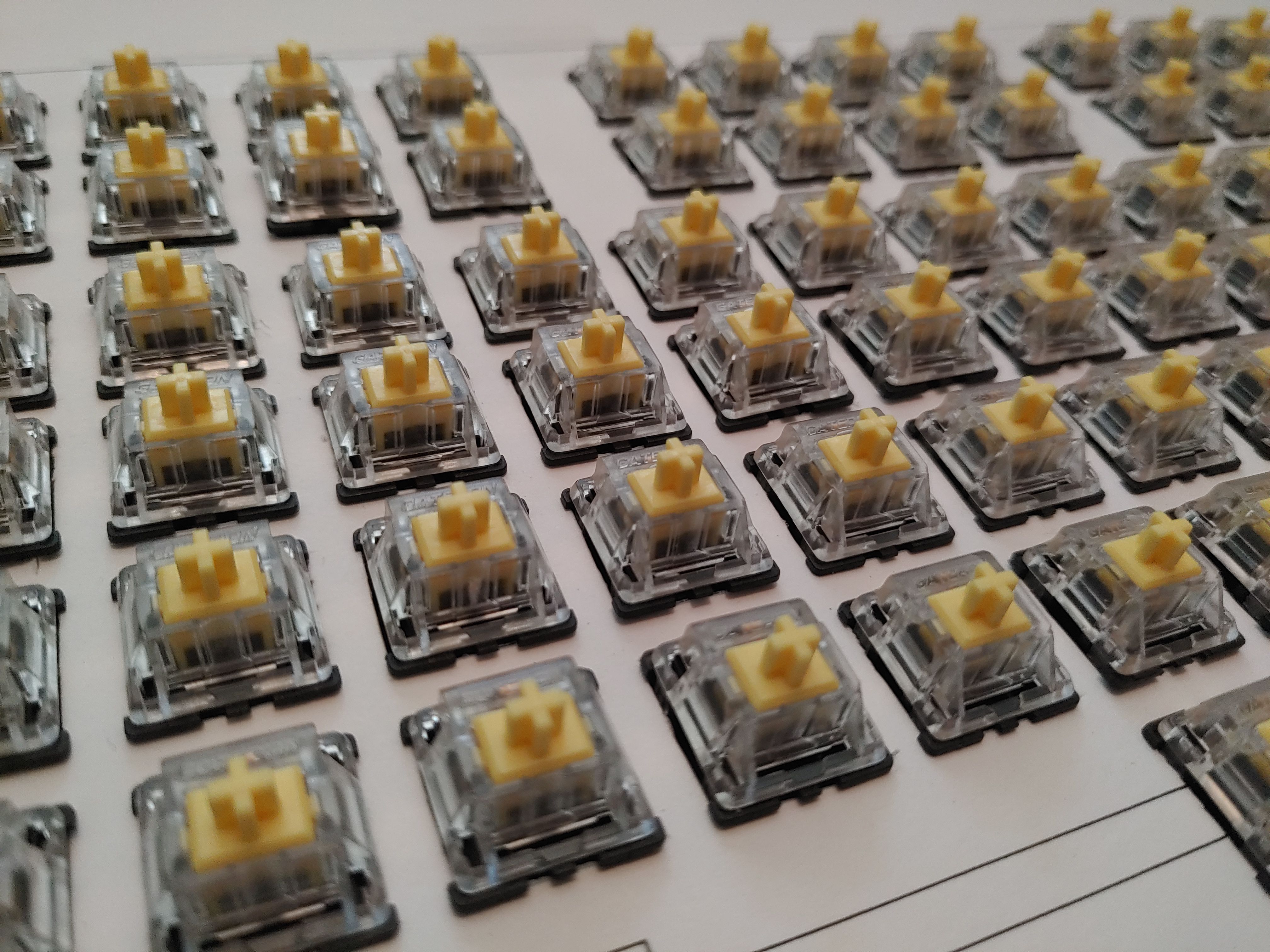
The layout has 118 keys, and I knew I wanted a few spares of each size. I went with 140×Gateron Yellow from KBDFans and 129×blank black PBT caps from NPKC.

For as long as I've been thinking about buying a mechanical keyboard, I've always imagined I would choose Blues for the clicky sound. But, I read various forum threads about clicky vs linear and saw that a lot of clicky users find them to be a nuisance after a while, or felt that actuation pressure should be learned by muscle memory instead of pushing through the click. Some day I'm sure I'll do another keyboard and I'd like to try clickies eventually, but I decided to do linear Yellows this time. Although typing on the linears isn't exactly quiet, you certainly can press keys silently if you need to. The typing experience is perfectly pleasant, and after only a few days of using the Nearer I found my rubber dome keyboard terrible in comparison.
Ordering the caps was kind of weird. The AliExpress page has product variant buttons for "100 pcs", "200 pcs", etc., but the seller has their own pricing scheme outlined in the product description. You're supposed to tell them what keys you need and they'll calculate a price by considering 2u keys to be 2× the price of 1u keys, and so forth, and that's how many "pieces" you need. Well that's not what AliExpress's variant ordering system is designed for, so I'm really not sure how this was supposed to go down. I just chose the variant that was close to, although a little bit less than the value that I calculated, and they accepted the payment without question. So I guess I got a discount. Your results may vary if you need pieces that aren't close to any of the variants.
Another thing I didn't expect is that the homing keys don't have raised bumps on them. Instead, the surface of the key has a deeper indent than the rest. Visually, it's very hard to distinguish, but in practice I'm not having any trouble with them.
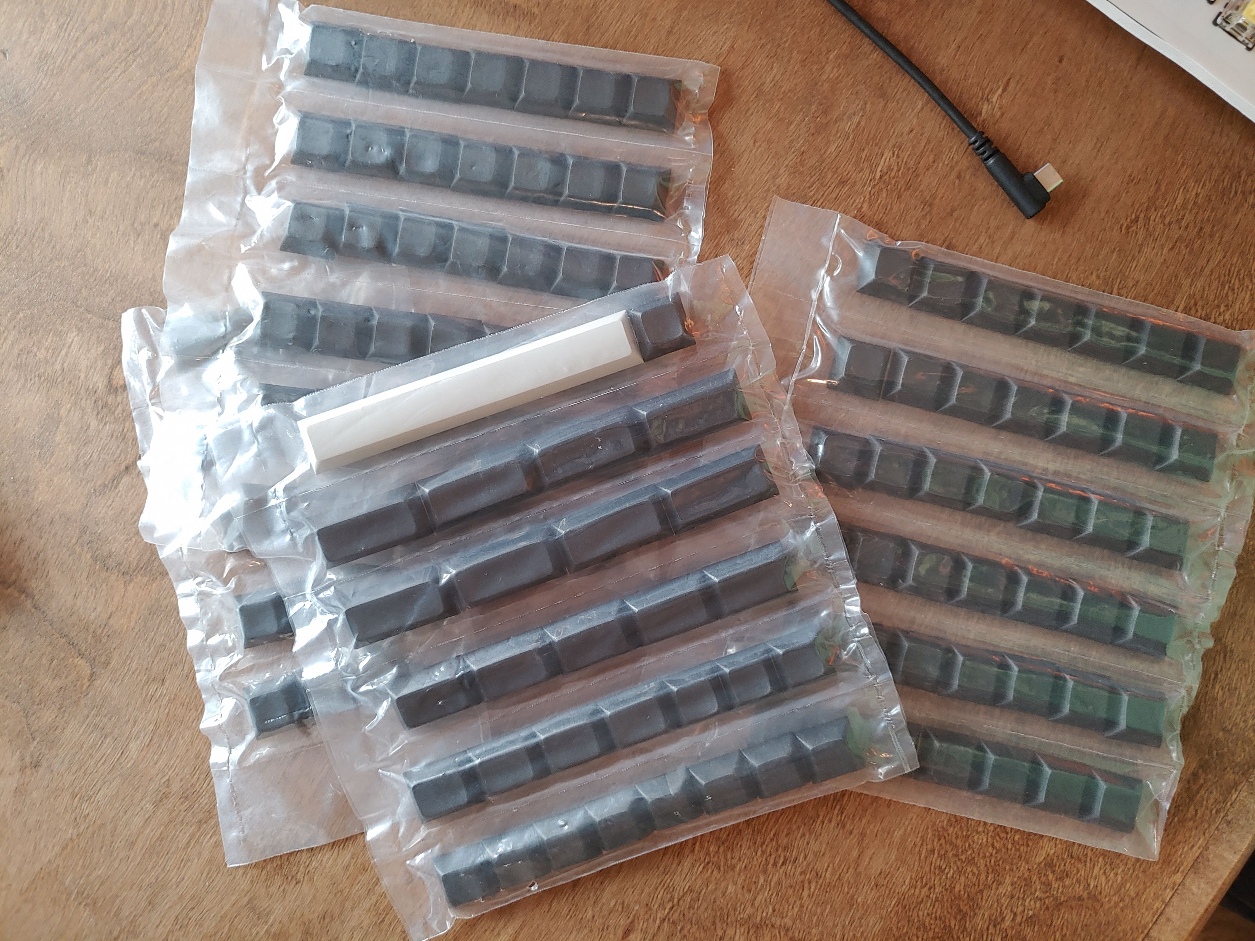
I've got 22 switches left over, either to use as repairs or just to play around with. I also made sure to buy at least two extra of each cap size.
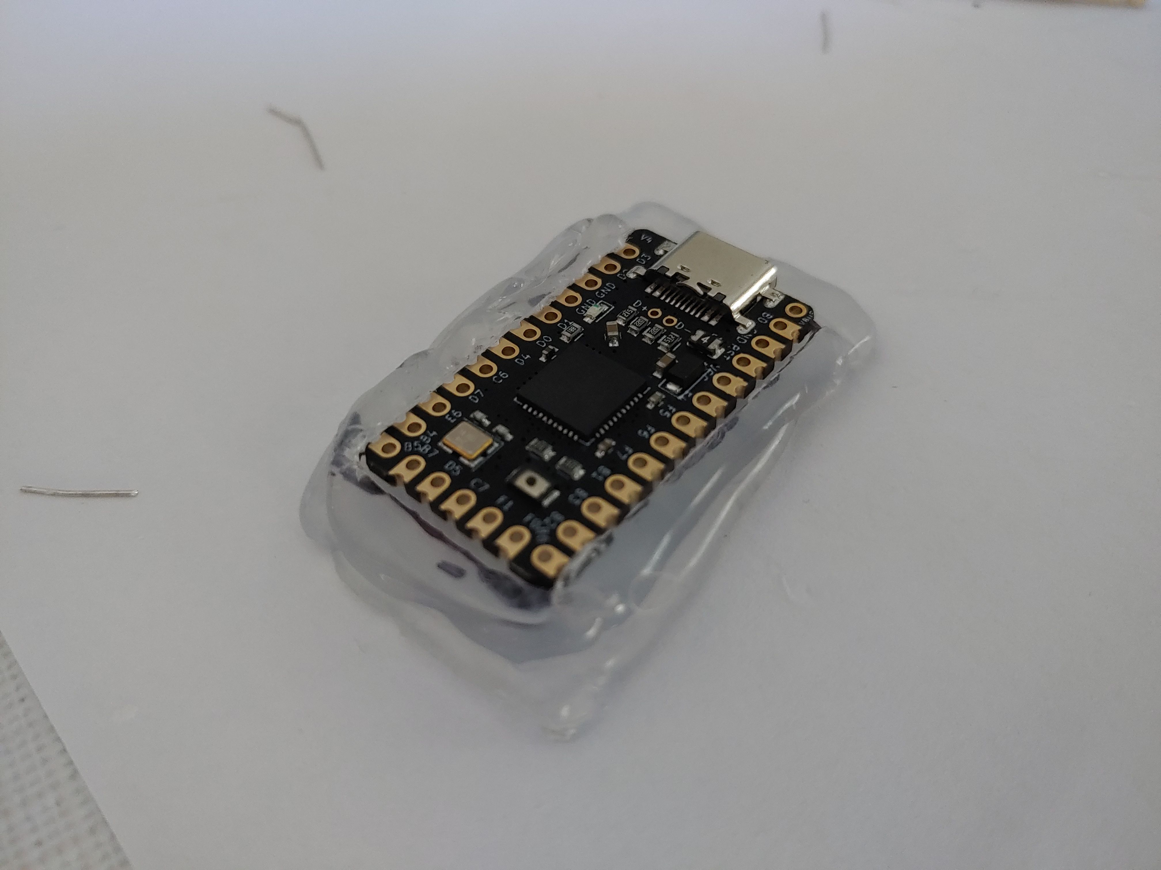
Microcontroller (§)
For the controller I chose the 24-pin Elite-C V4 because I wanted to use USB-C. That's pretty much the only reason.


Designing the switchplate (§)
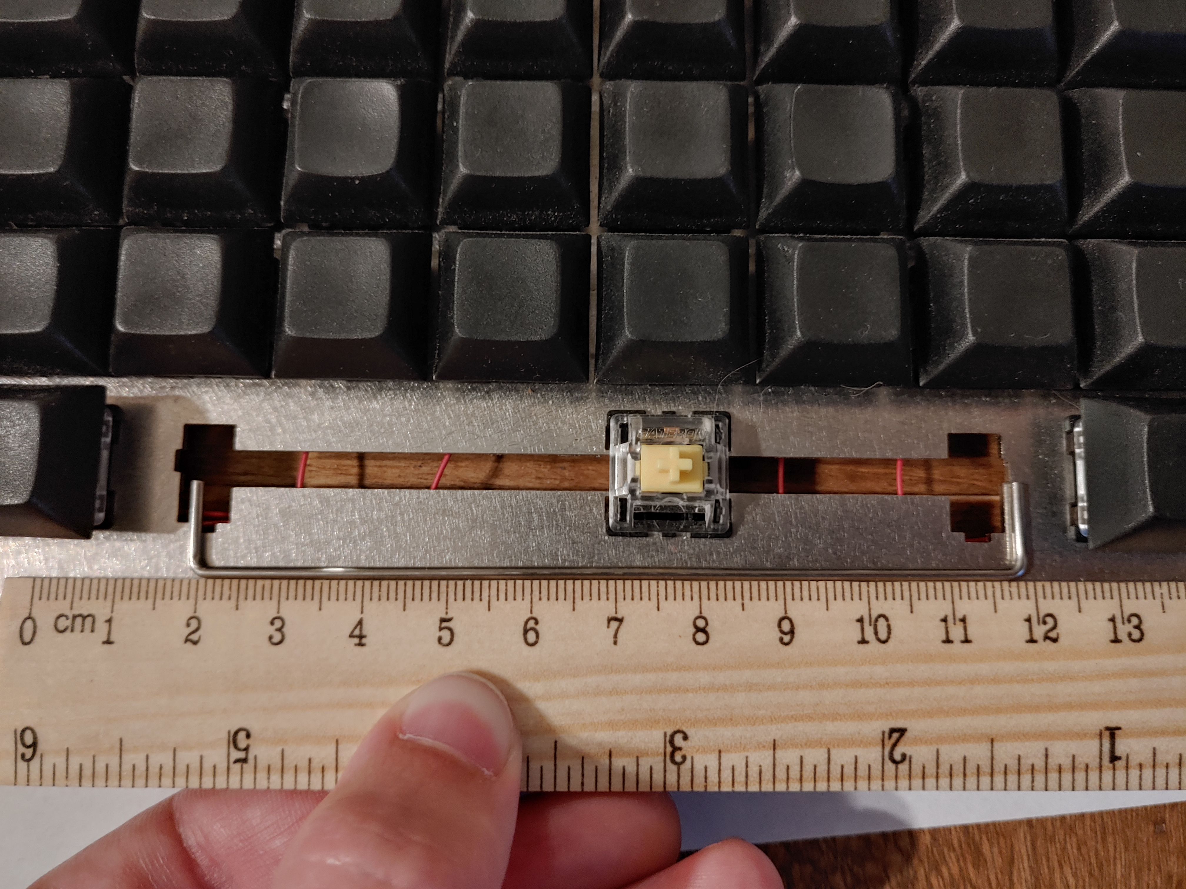
The switchplate is made by taking the output of keyboard-layout-editor and pasting it into builder.swillkb. I chose an 8mm edge padding, 8mm edge radius, and a couple of 2.1mm holes so I can use 2M screws.
If I were to do this again, I'd give myself a little more padding between the screw holes and the edge of the plate, and I'd add more intermediate screw holes. My switchplate has a very slight bend to it and I don't have any means of making it perfectly flat, so a few extra screws would help me get the plate to sit more flush against the base.

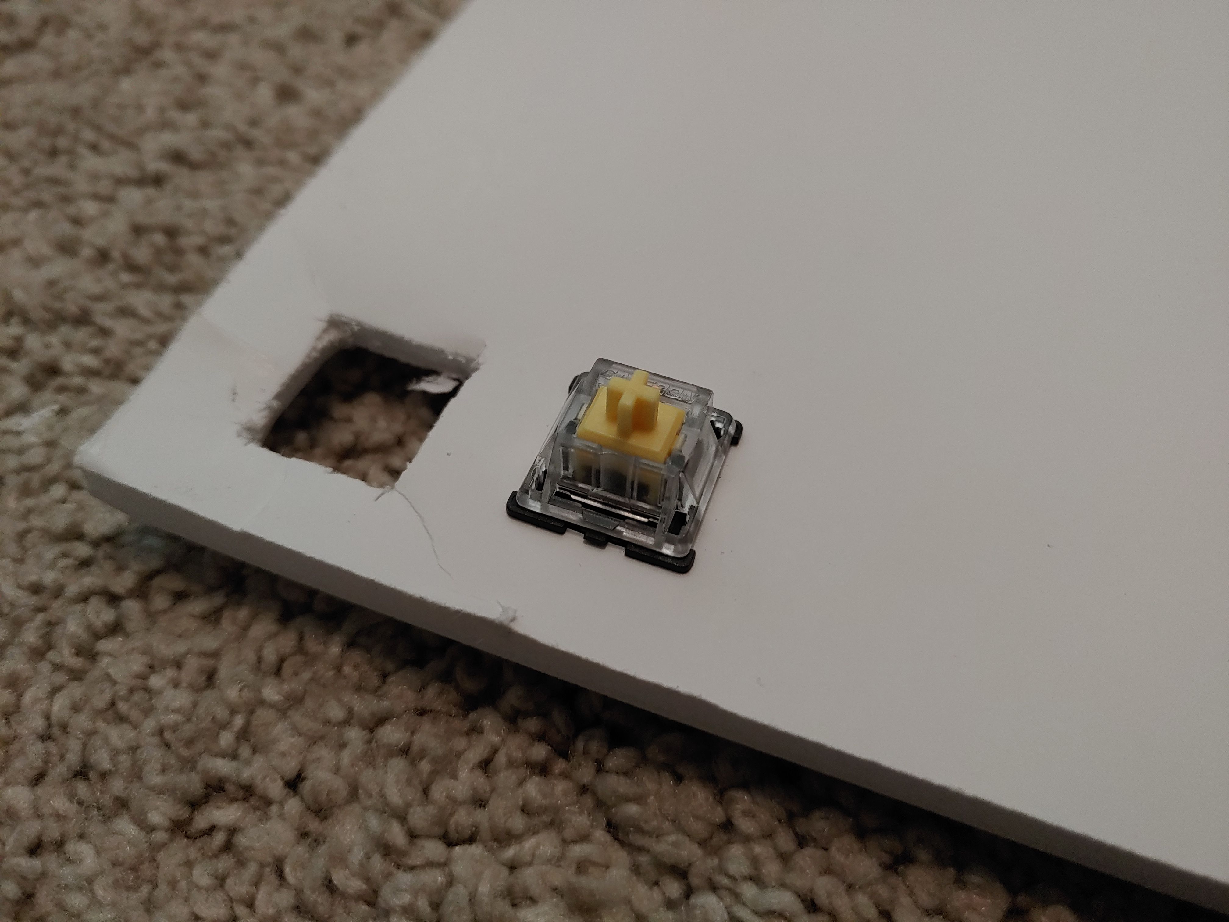
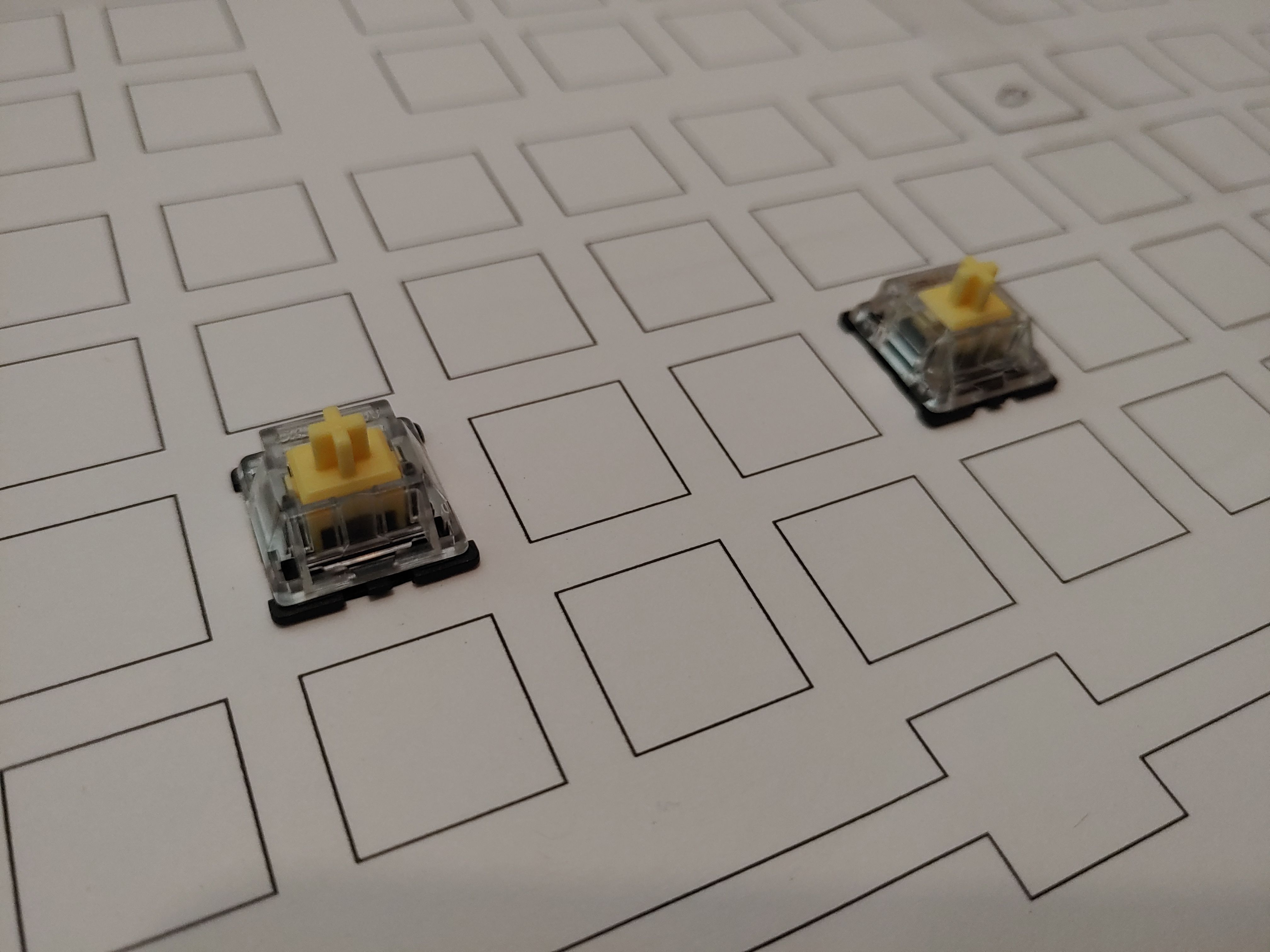
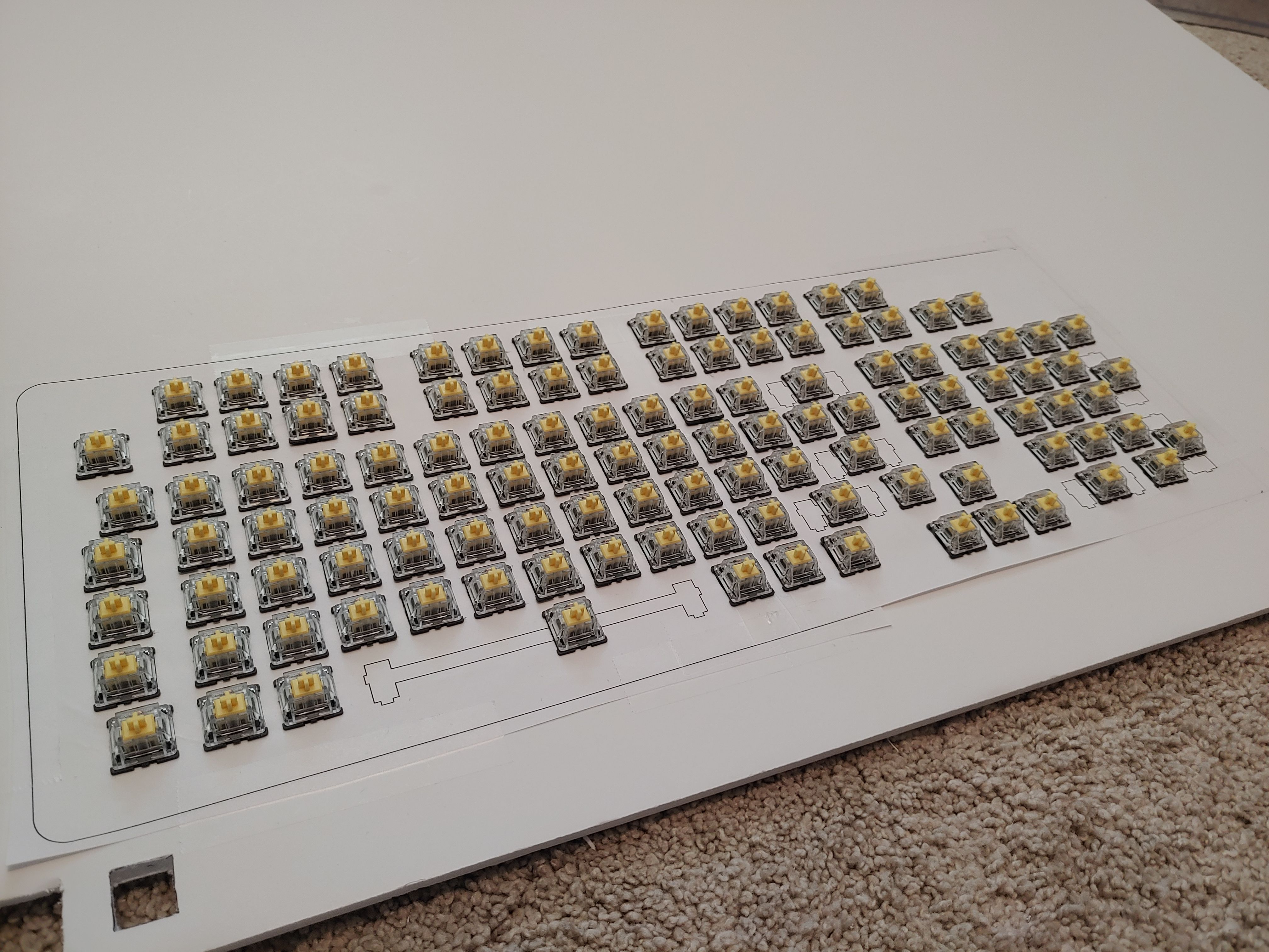
Because this layout would be totally new to me, I knew I needed to be comfortable with the design before having it cut in metal. I bought a foam posterboard, printed the layout on paper, and spent about four hours across a couple of podcast-listening sessions to cut out each switch hole with a craft knife.
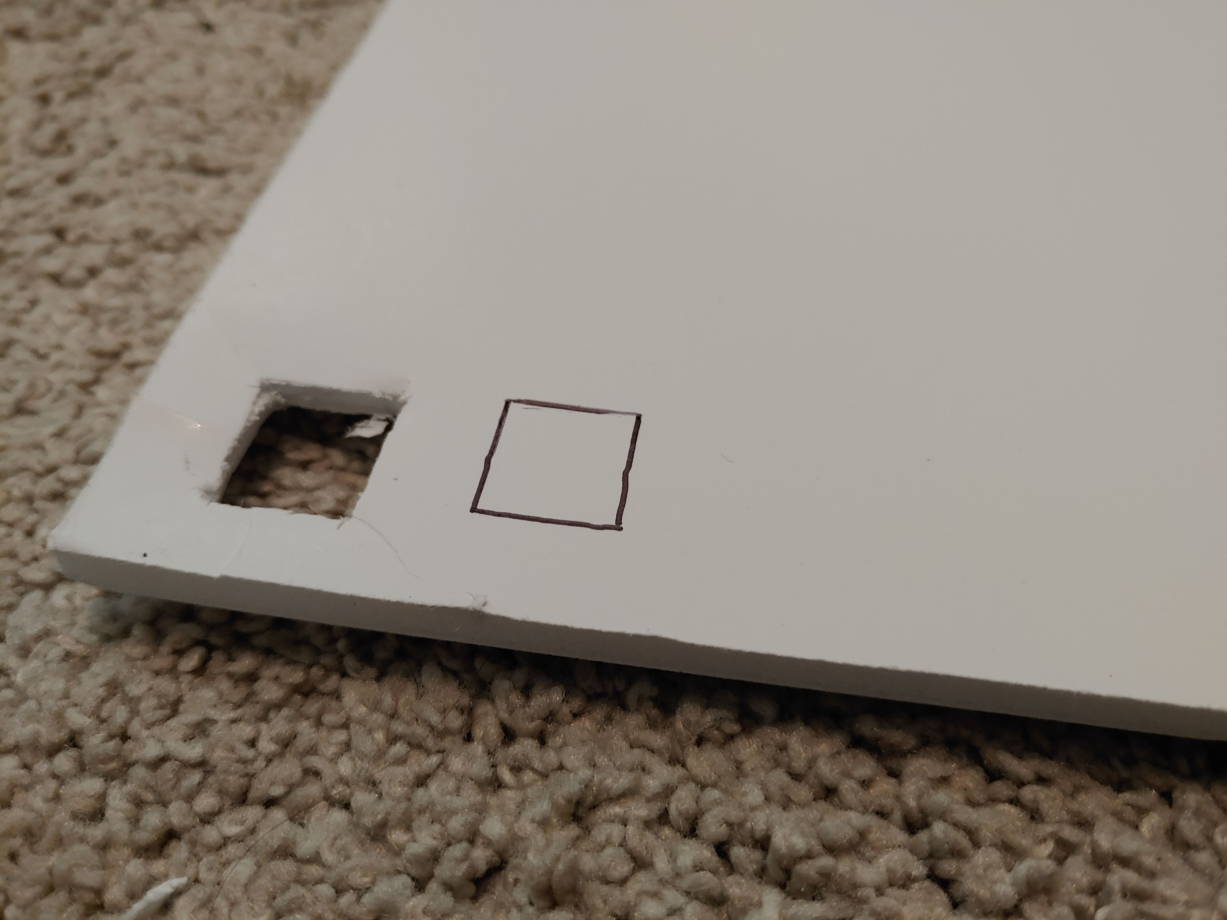
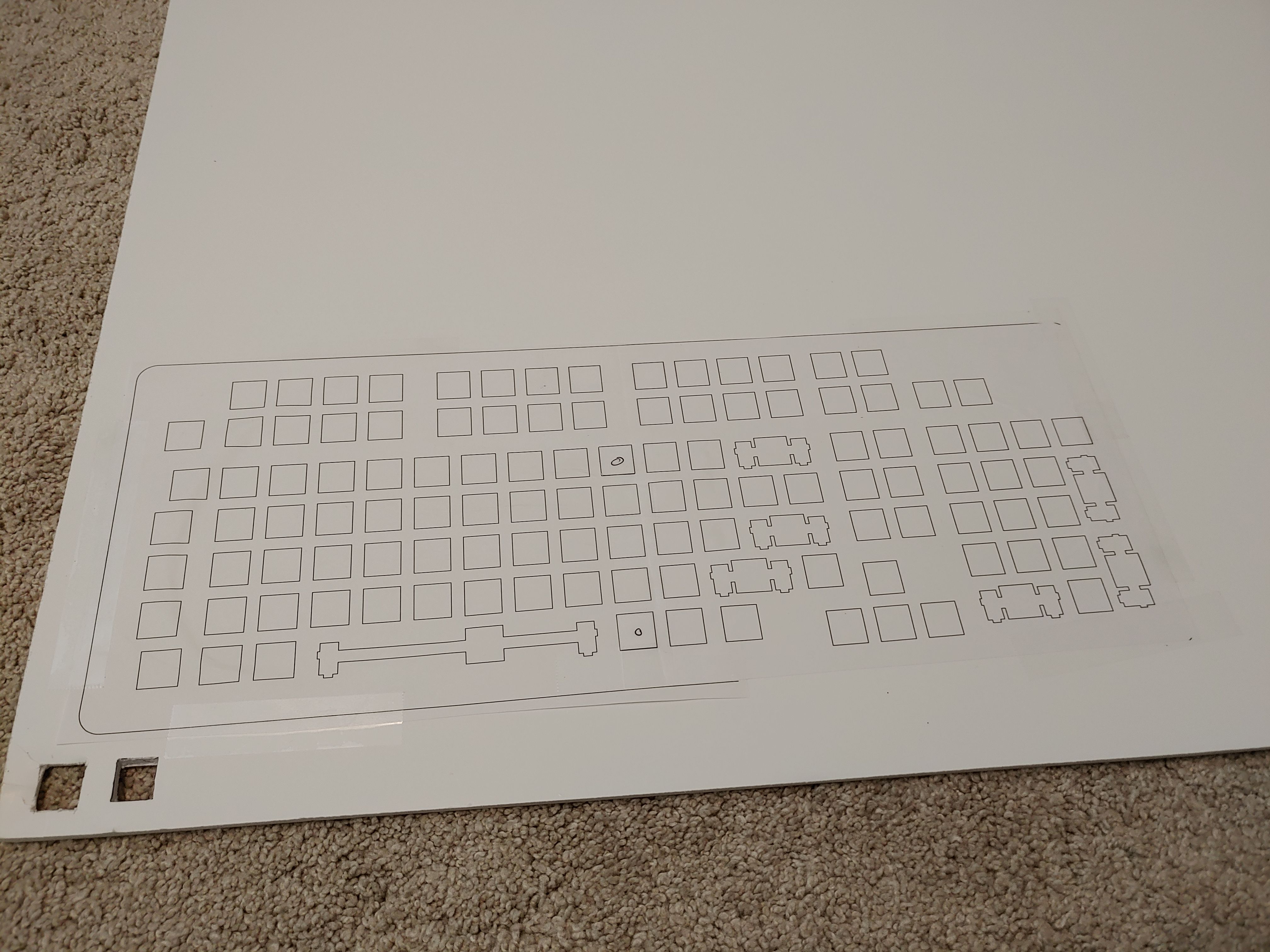

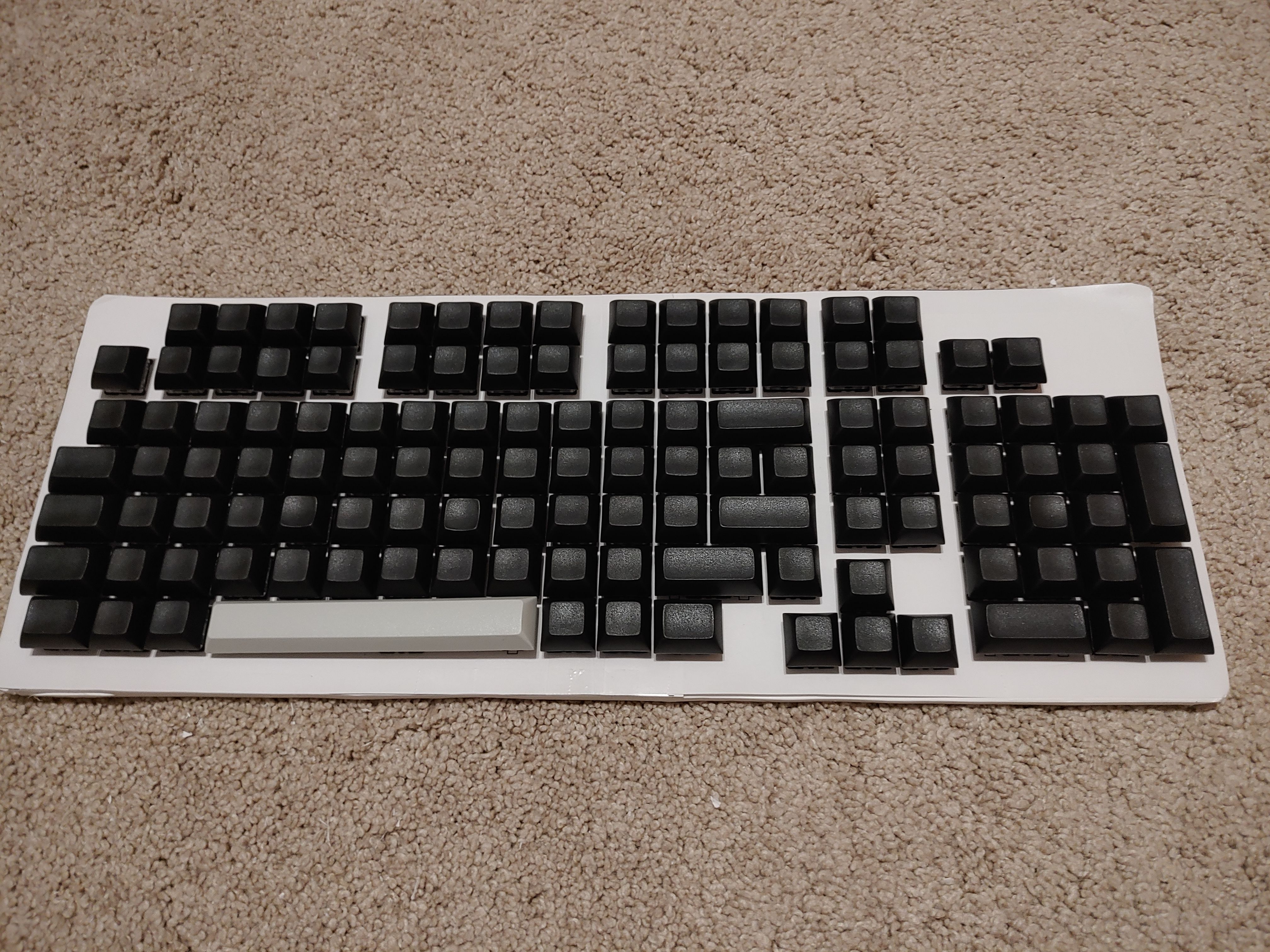
I'm sure you're wondering about the gray spacebar. This was in fact the result of spontaneous inspiration, an experience not much different from true enlightenment, which came to me after an intense bout of deeply personal meditation and was fully crystalized when the keycap vendor said "We don't have 6u space in black, only in gray".
This prototype was definitely worth the time, because this is the point where I changed Ctrl from 1.25u to 1.5u. If I hadn't bought extra 1.5u caps, that wouldn't have been possible.
After generating the final switchplate on swillkb, I had it cut through LaserBoost. Swillkb has a partnership with LaserGist, but I found that LaserGist's price before shipping was about $20 higher than LaserBoost's price after shipping. I tried comparing a few other options, but most either don't have instant price quoting or the prices weren't any better than LB.
Switchplates should be 1.5mm thick for Cherry-style switches, which includes the Gaterons.
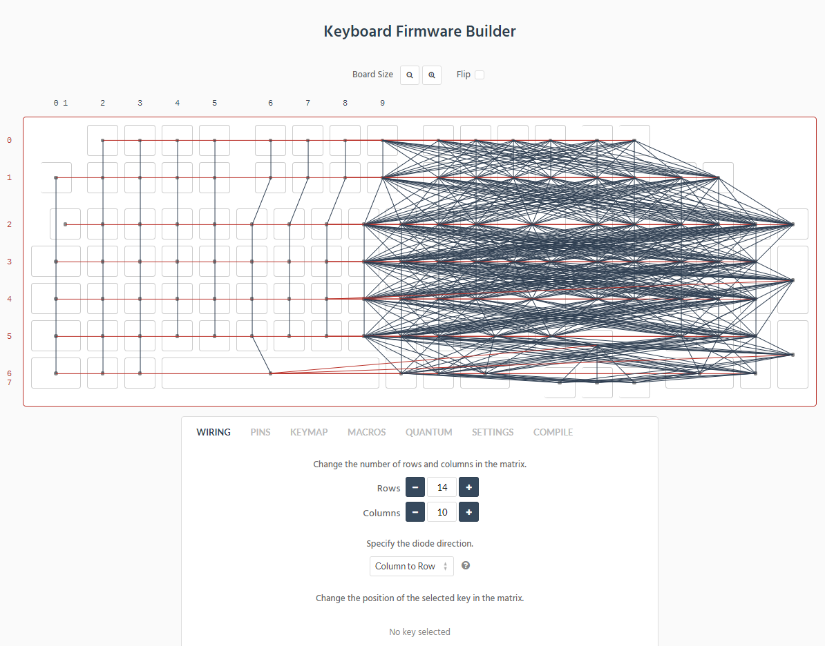
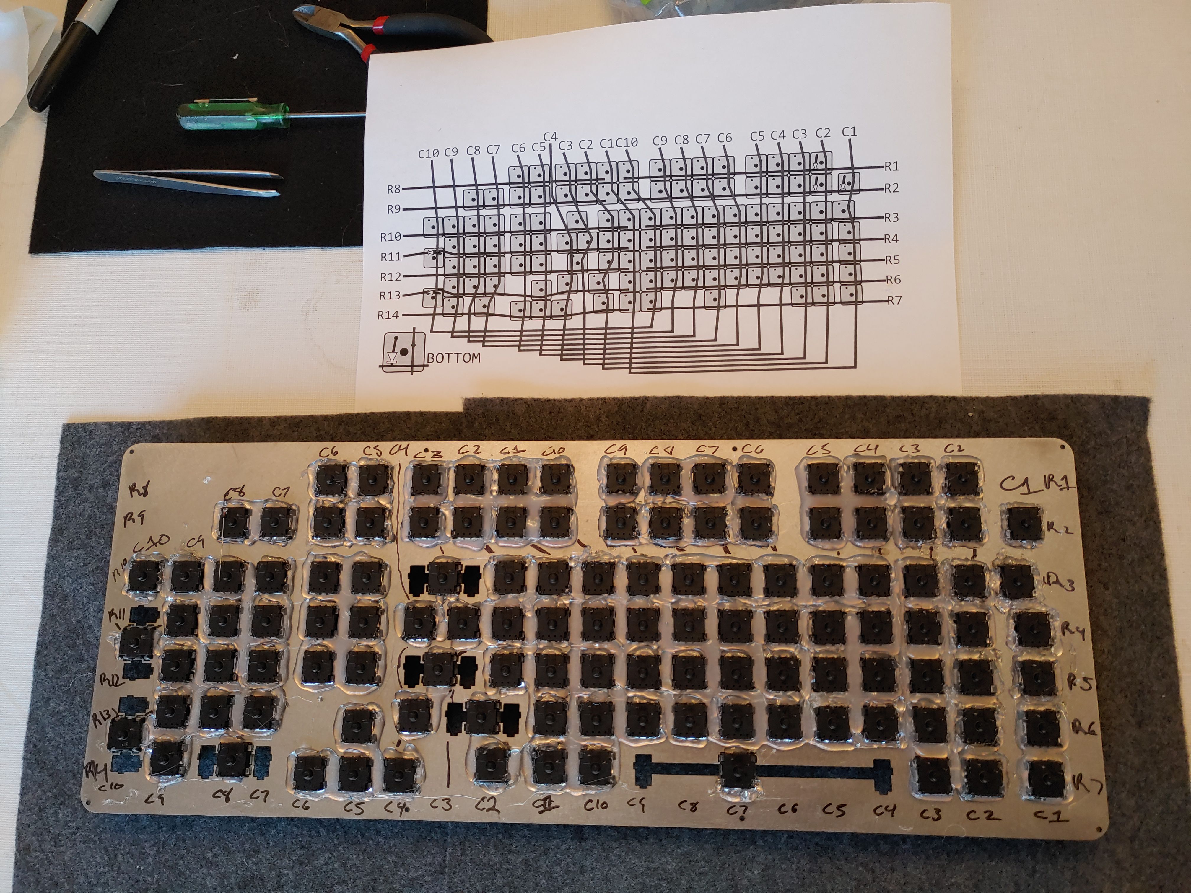
Designing the wiring matrix (§)
While the plate was still in the mail, I started working on the wiring matrix. This was the first time I had ever put together a piece of electronics and it was a great learning experience.
Each key switch has two posts on the underside. Keyboards are wired with one post connected to a "column" wire and the other connected to a "row" wire. The controller sends signals out via the column wires, one column at a time, and listens to the row wires to see where the signal comes back. In effect, every key has an X, Y coordinate which the firmware then maps to letters / keycodes.
A simple matrix for my keyboard would look like this:

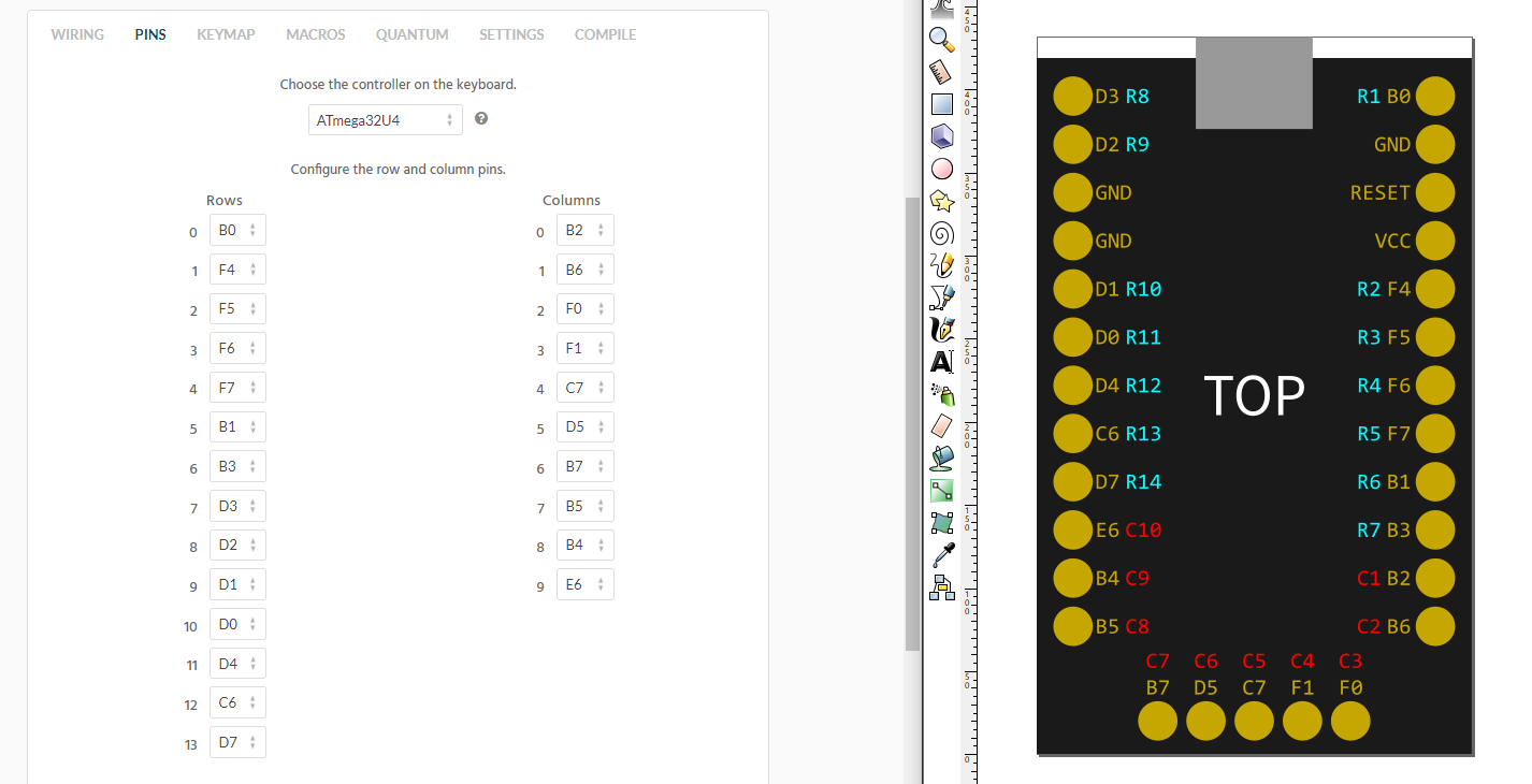
But, there's a problem. Each of these wires needs to be soldered onto a separate pin of the controller, which means the controller must have at least rows+columns available pins. That means I'd need 27 pins, but the Elite-C only has 24.
The solution is what's called a duplex layout, where two physical columns are wired together as a single virtual column. Here's mine:

The duplex layout halves the number of columns in exchange for doubling the number of rows. That brings me to 10+14=24 exactly. This does mean I have no pins left for Caps Lock or Num Lock LEDs. Instead, Caps Lock is indicated by pushing a button and seeing a capital letter come out.
If you're willing to sacrifice your sanity to achieve maximum keyboarditude, the maximum number of keys you can address is (pins/2)² — a 12×12 matrix with 144 keys in this case. You might have to do some gymnastics with your wires, since the physical layout would be far removed from the virtual layout, but it would be possible. Keep in mind that the controller doesn't know or care about the physical positions of the switches, as long as each one has a unique X, Y coordinate via the row and column wires.
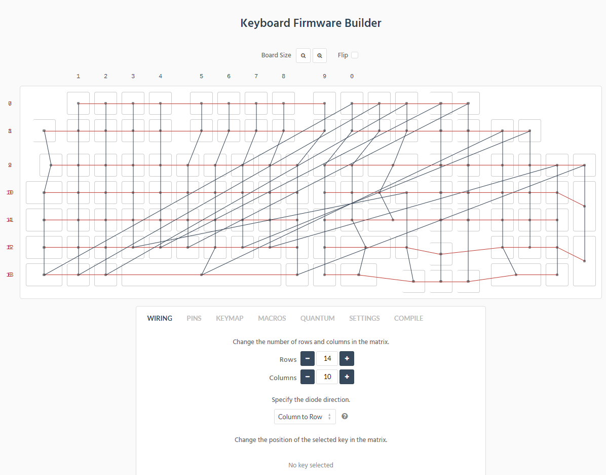
Anyway, here's the wiring diagram as seen from the underside, which is how we'll actually work on it, and in more realistic detail:

And the wires join up to the controller like this:

You're seeing the final versions of these images, but make no mistake — this took several iterations to get right. In fact, while I was soldering the wires I realized that I had imagined it differently and just changed the design right then. You can optimize your controller pin mapping to reduce the length and overlaps of your wires, but it's not a big deal. Whatever happens, you can adjust the firmware to match whatever you put together.
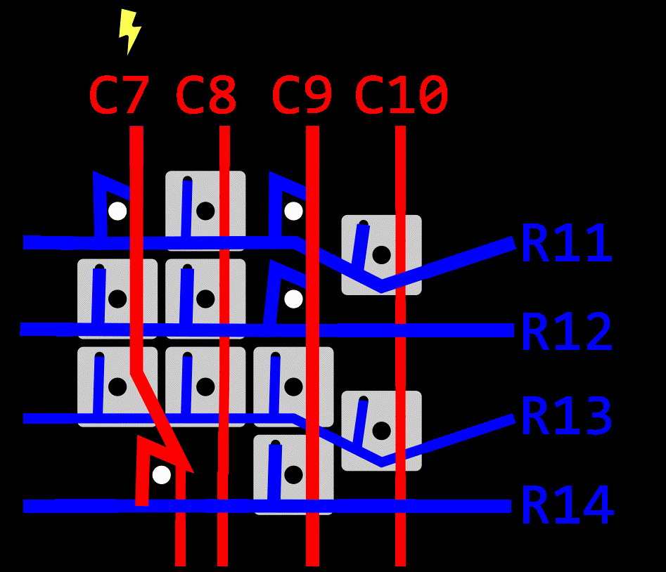
If you've seen other keyboard builds, you'll know that the wiring matrix requires diodes. I bought these 1N4148 diodes.

I know what diodes do — they allow electricity to only flow in one direction — but it took me a bit of studying to figure out how that applies to keyboards. I put together this drawing to illustrate my findings. In this picture, the black keys are the ones being pressed. Remember that the controller sends a signal out through one column at a time and listens to the rows, so here's C7 being lit up:

The signal from the column wire is transfered through the switch and diode to the row wire, telling the controller the row coordinate of the pressed keys in the C7 column. The controller sees R11 and R14, so the pressed keys are C7+R11 and C7+R14, 7 and 0.
If your keyboard doesn't have diodes, certain combinations of keypresses can carry the signal to places that trick the controller into believing some other keys are being pressed when they actually aren't. Notice how the signal is flowing through the 9 key in the wrong direction, from a row to a column, which lights up the C9 column. Even though 6's actual coordinate is C9+R12, the controller only knows that it sent a signal on C7 and got a response back on R12, so it thinks C7+R12 is pressed, which is 4.
Building the firmware (§)
The plate was still in the mail at this point, and I felt confident about the wiring design, so I began doing the firmware on kbfirmware.com. Once again, the keyboard community has done all the hard work. All I'm doing is plugging in my information.
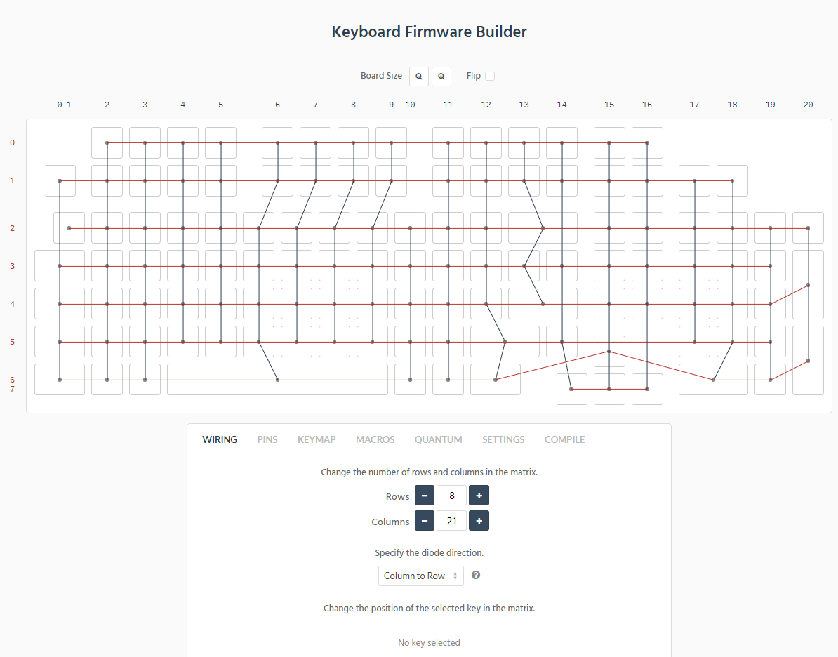
Not so fast, kbfirmware. Don't you know we're doing a duplex layout?
Yeah, that's right, that's just how I like my duplex layouts.
As it happens, kbfirmware uses the exact opposite red/blue color scheme that I chose, but you can see how those diagonal jumps represent the long bridges I drew, connecting two physical columns into a single virtual column.
I drew my controller diagram with row and column numbers starting from 1, but on kbfirmware they start from 0. Filling in this table is a good workout for your looking-back-and-forth muscles, often underrepresented in other workout routines.
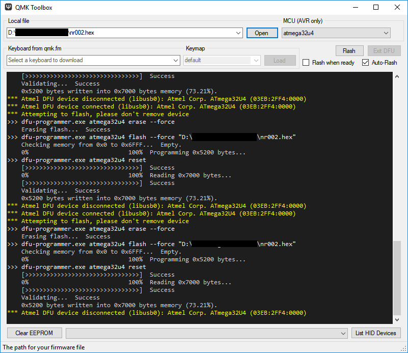
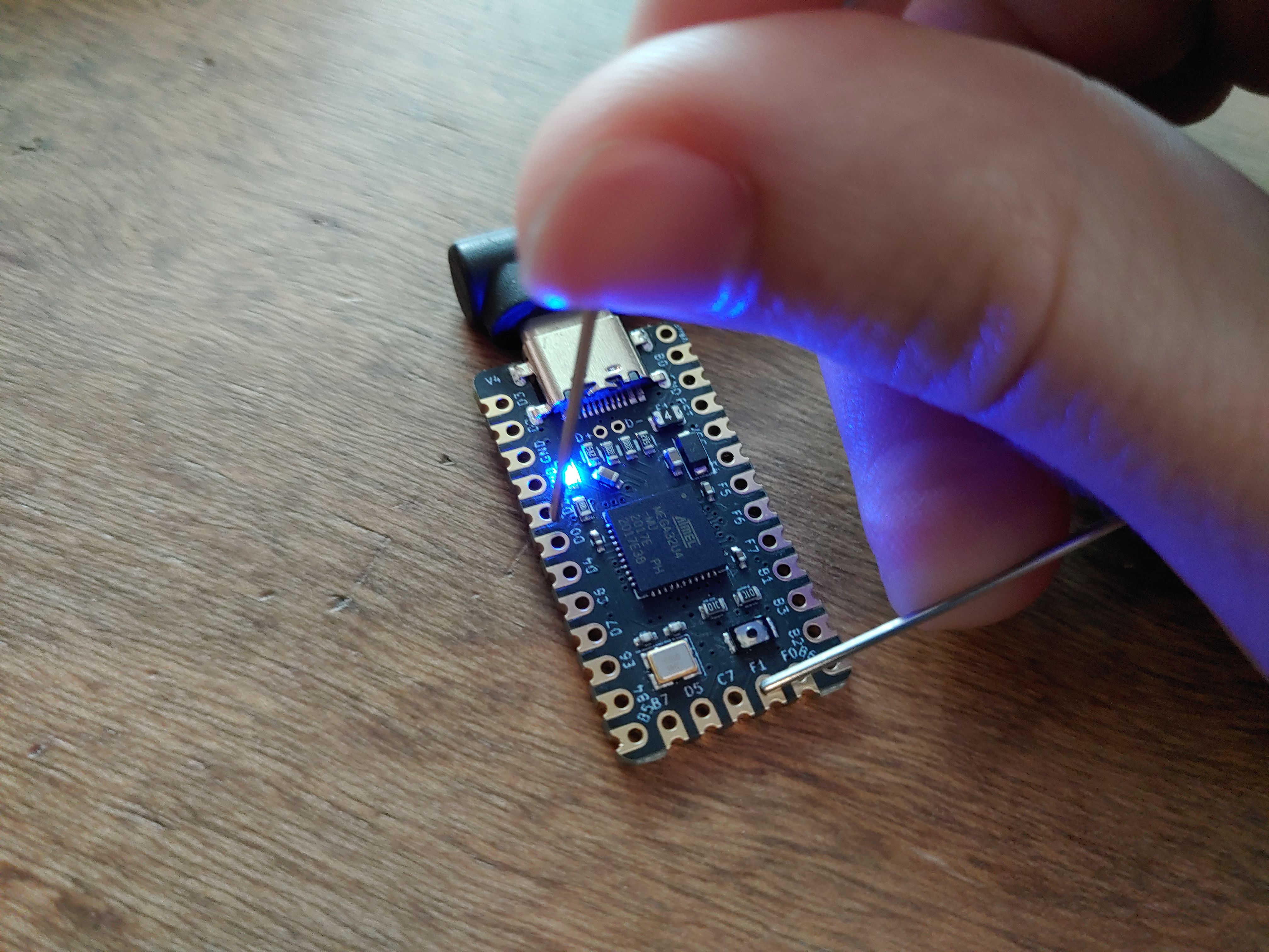
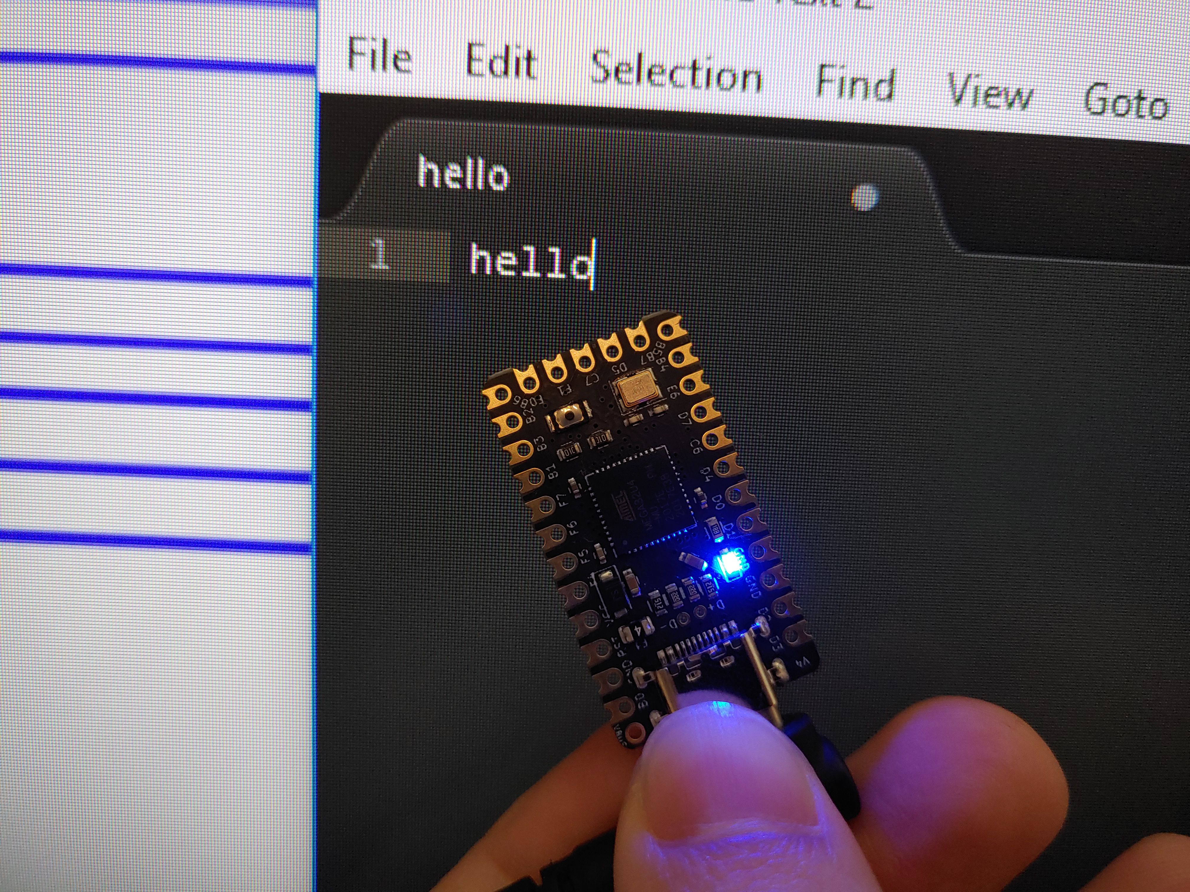
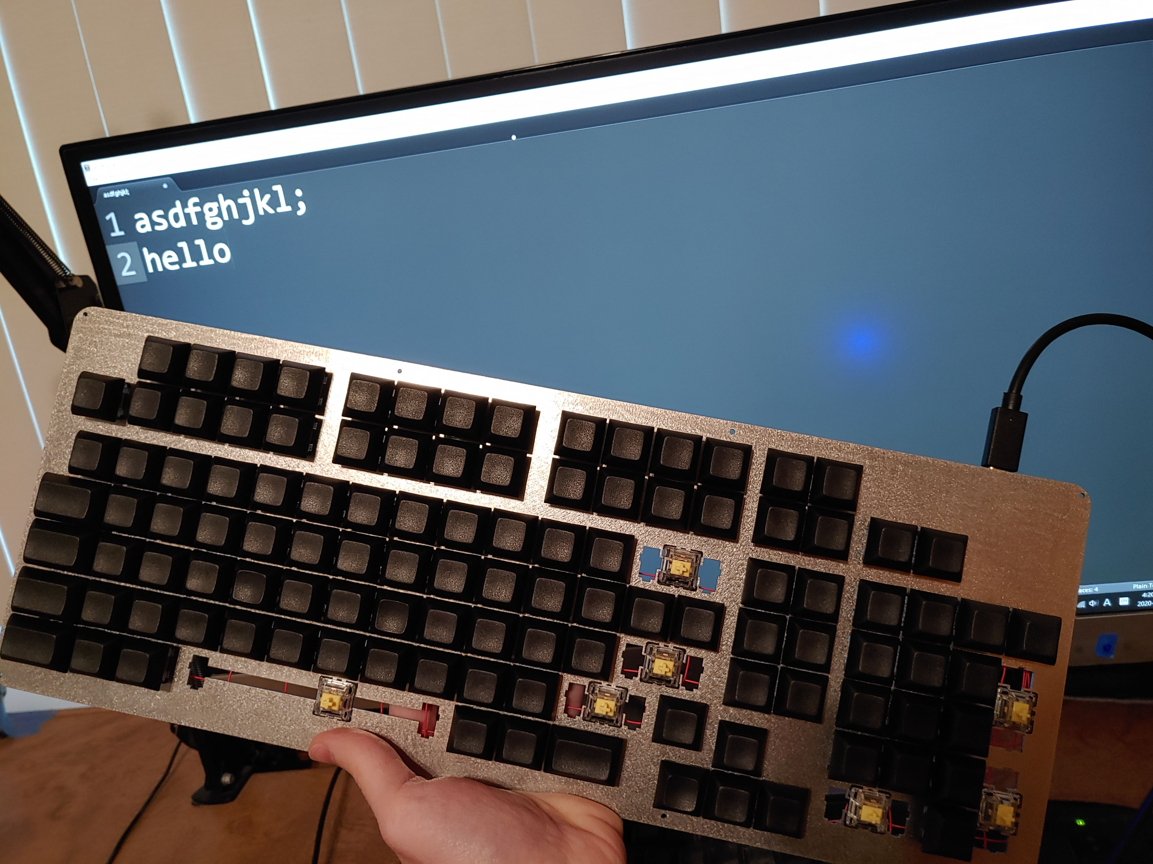
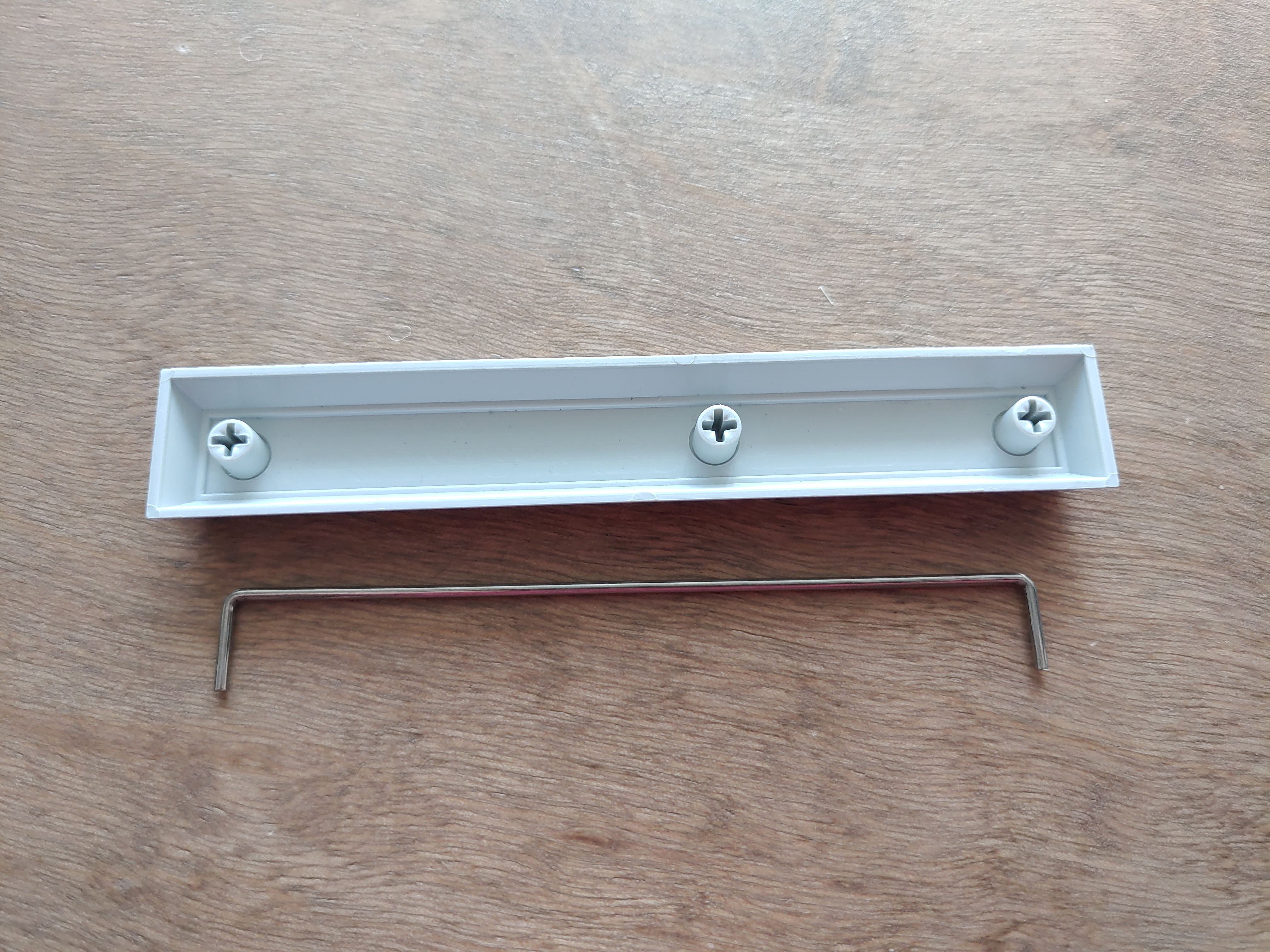
After downloading the firmware as a .hex file, it is loaded onto the controller using QMK Toolbox. It did everything perfectly on the first try. Just turn on auto-flash, and use a paperclip or piece of wire to short RESET to GROUND twice to reset the microcontroller.

Then, you can simulate keypresses by shorting a column pin to a row pin. And you can just end the whole project here, really. The rest of the keyboard is basically just decoration. It's functional as is.
Arrival of the switchplate (§)
The switchplate came in the mail:
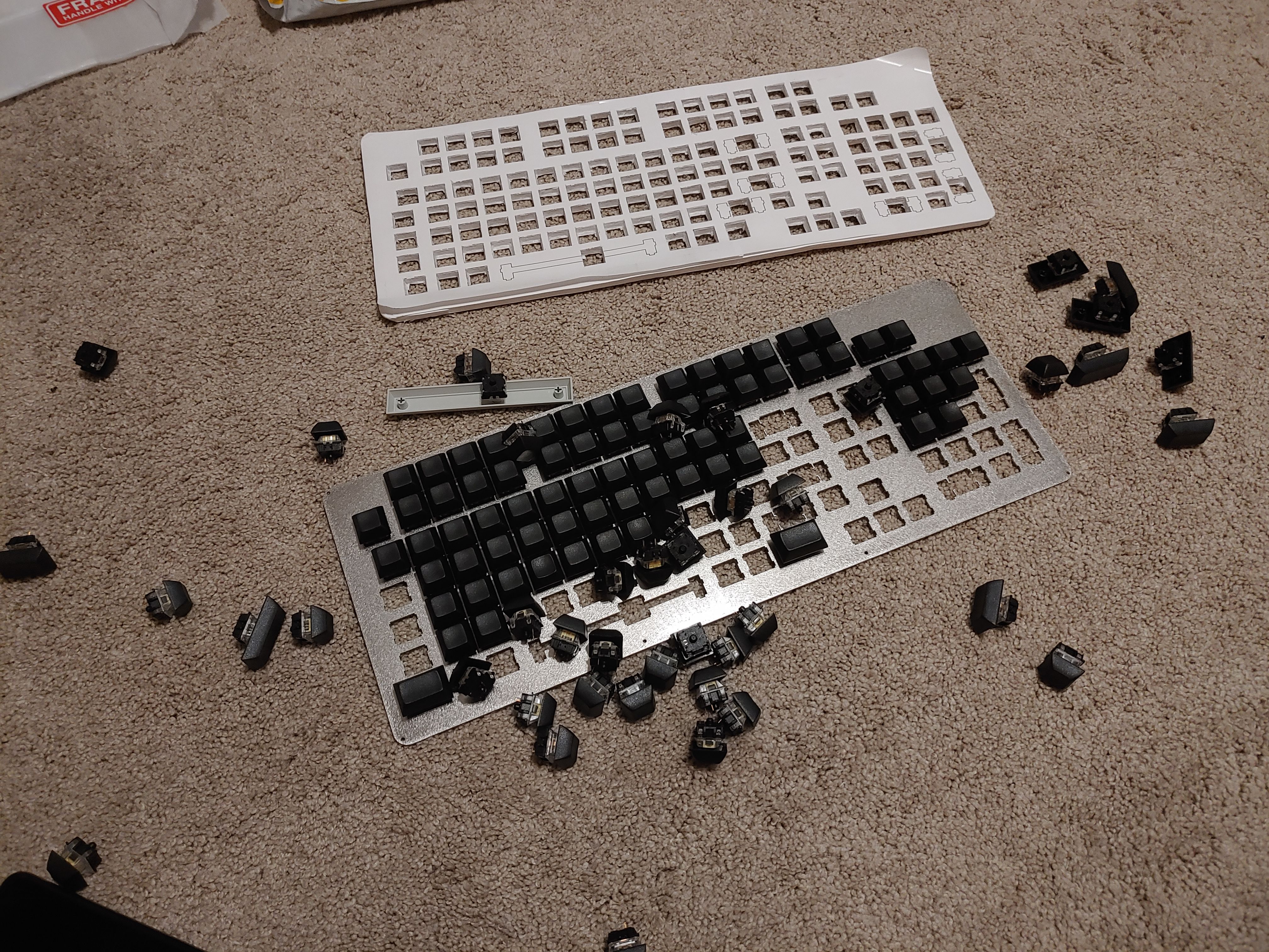
But something must have been wrong with the laser that day, because the plate had some alignment defects to the tune of 1mm in a couple of places. Normally I'm not one to complain to support, but this was expensive and beyond their stated tolerances. I took some pictures demonstrating the alignment with a ruler and some MS Paint annotations:


LaserBoost immediately offered to express-mail a replacement for free. So in the end everything turned out fine.

I wouldn't want to miss this opportunity to show off how I transfered the switches from the first plate to the new plate. The cap- and switch-pullers I ordered in the mail wouldn't arrive for at least another month.

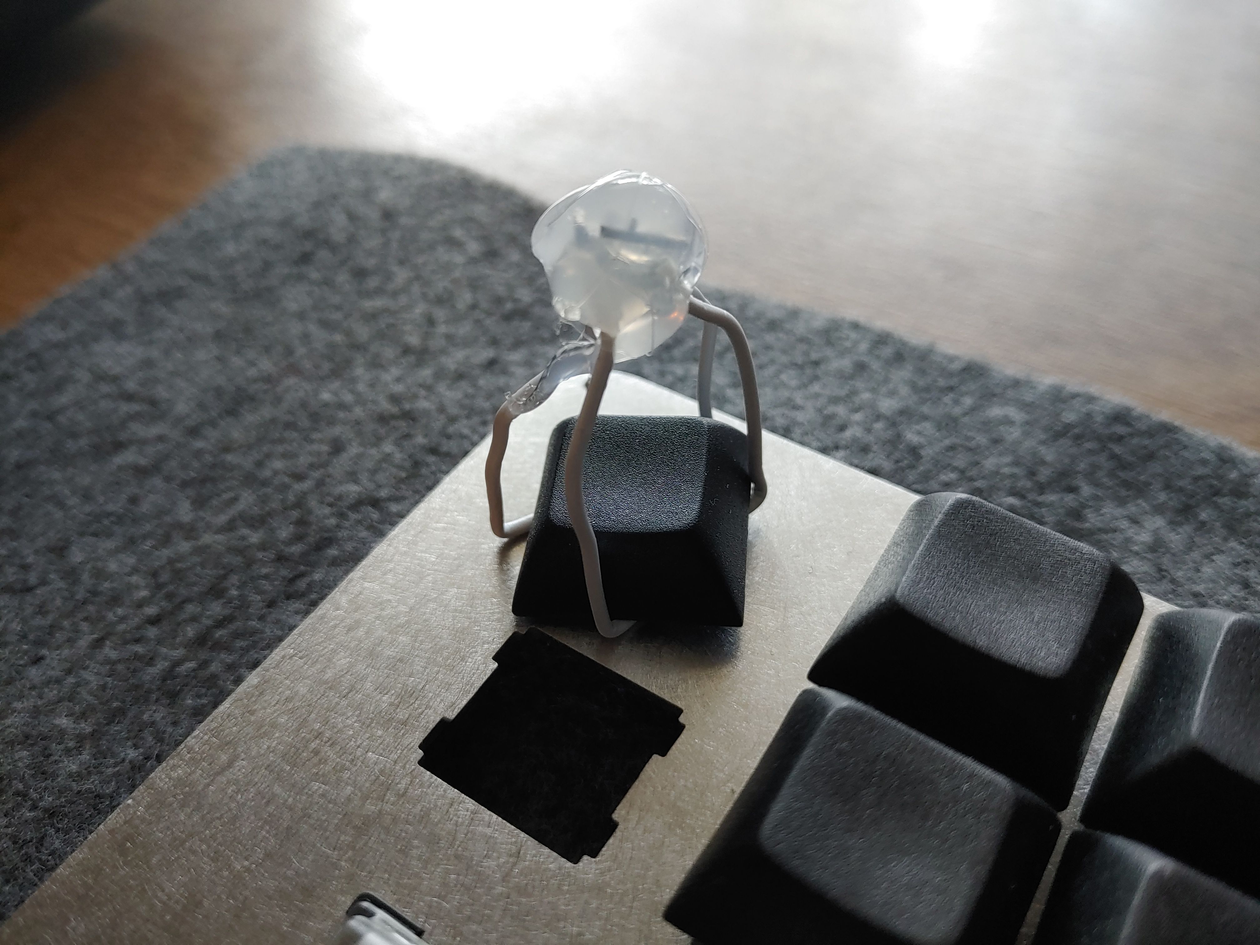
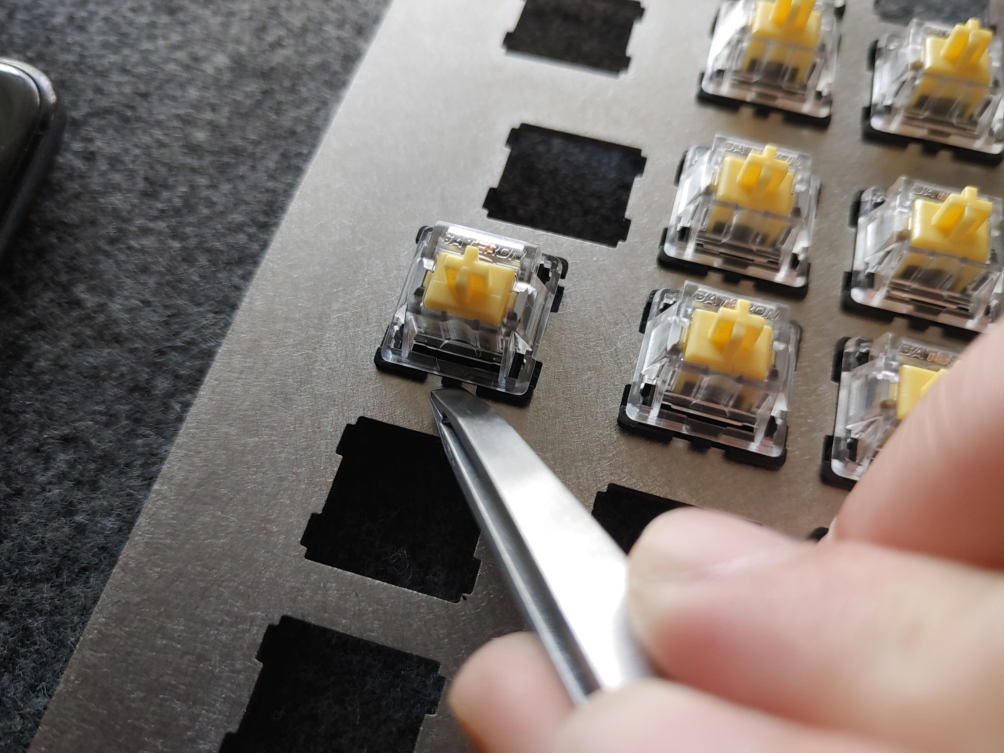
That's right, everyone. When you buy cap- and switch-pullers for $1.00 on ebay, you're giving in to Big Puller's brainwashing. Paperclips and tweezers were all you needed all along.
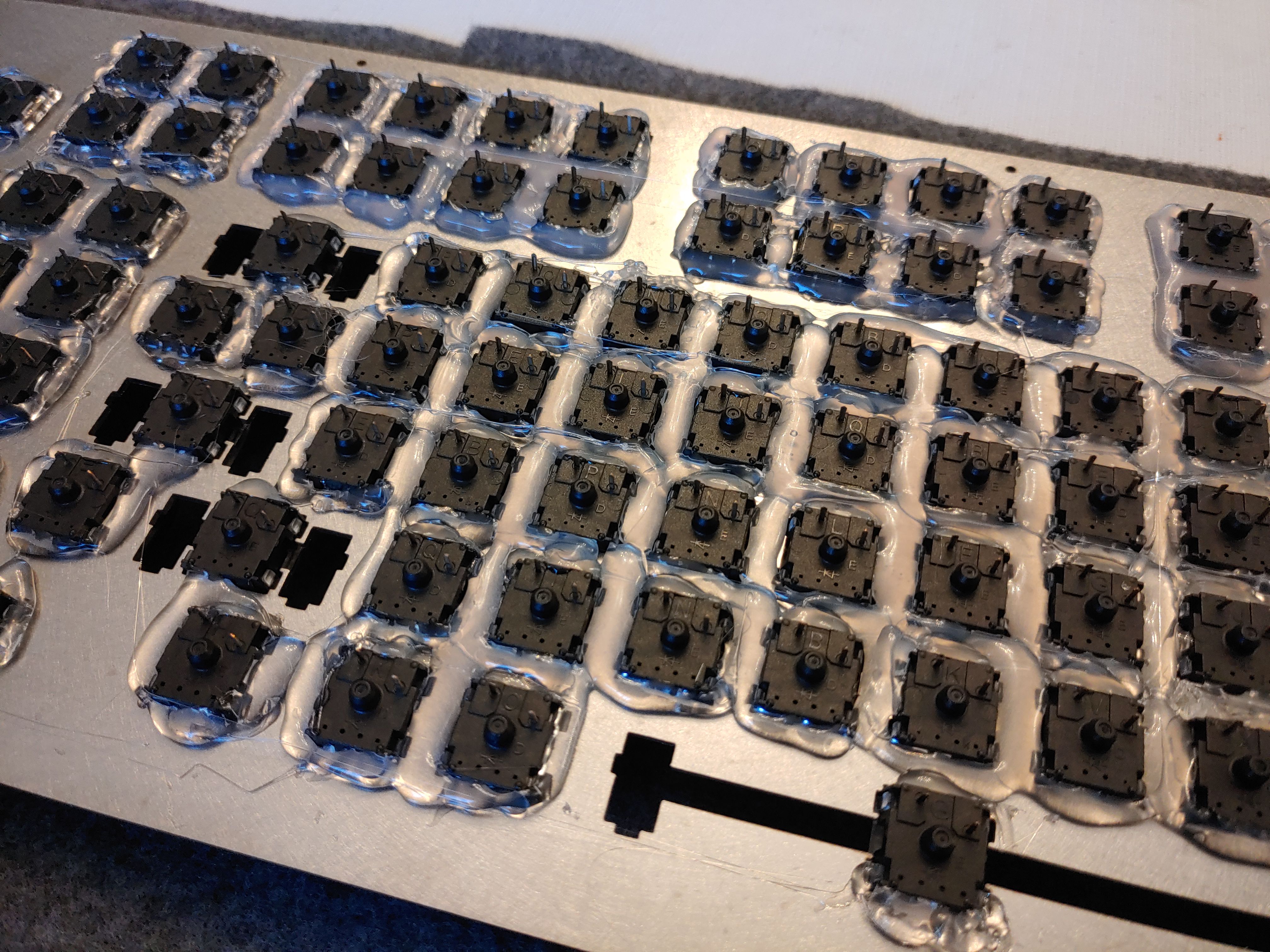
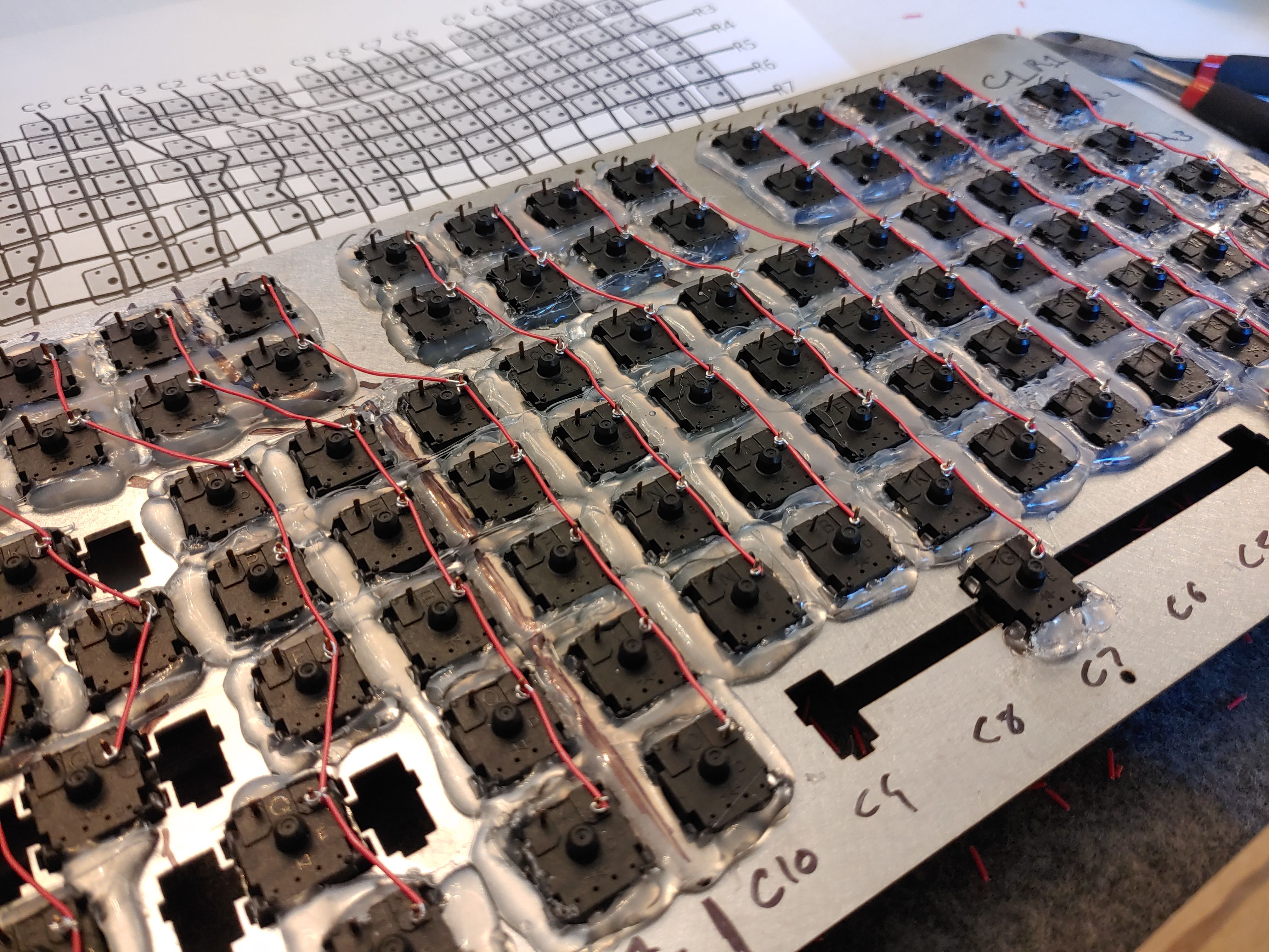
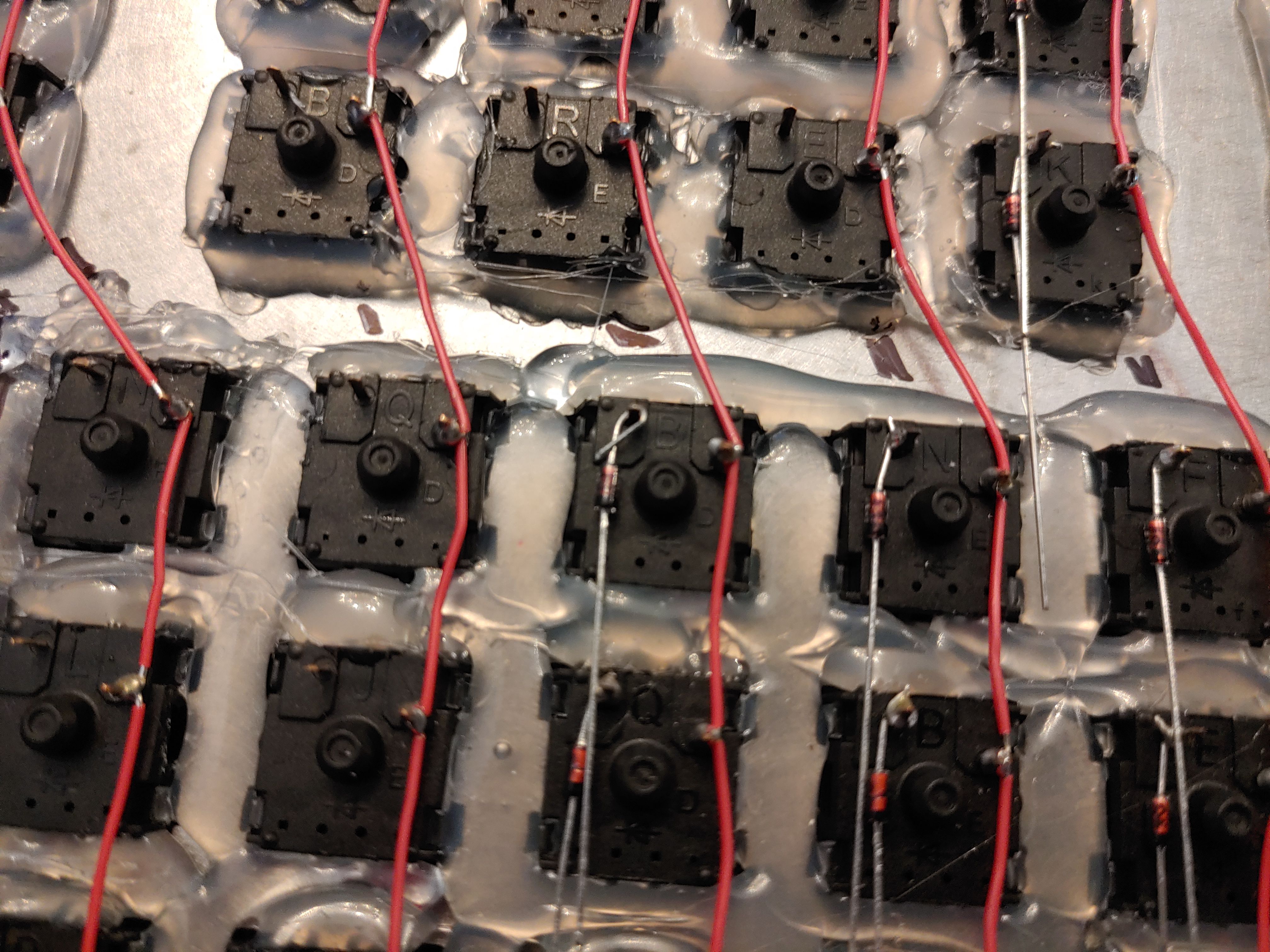
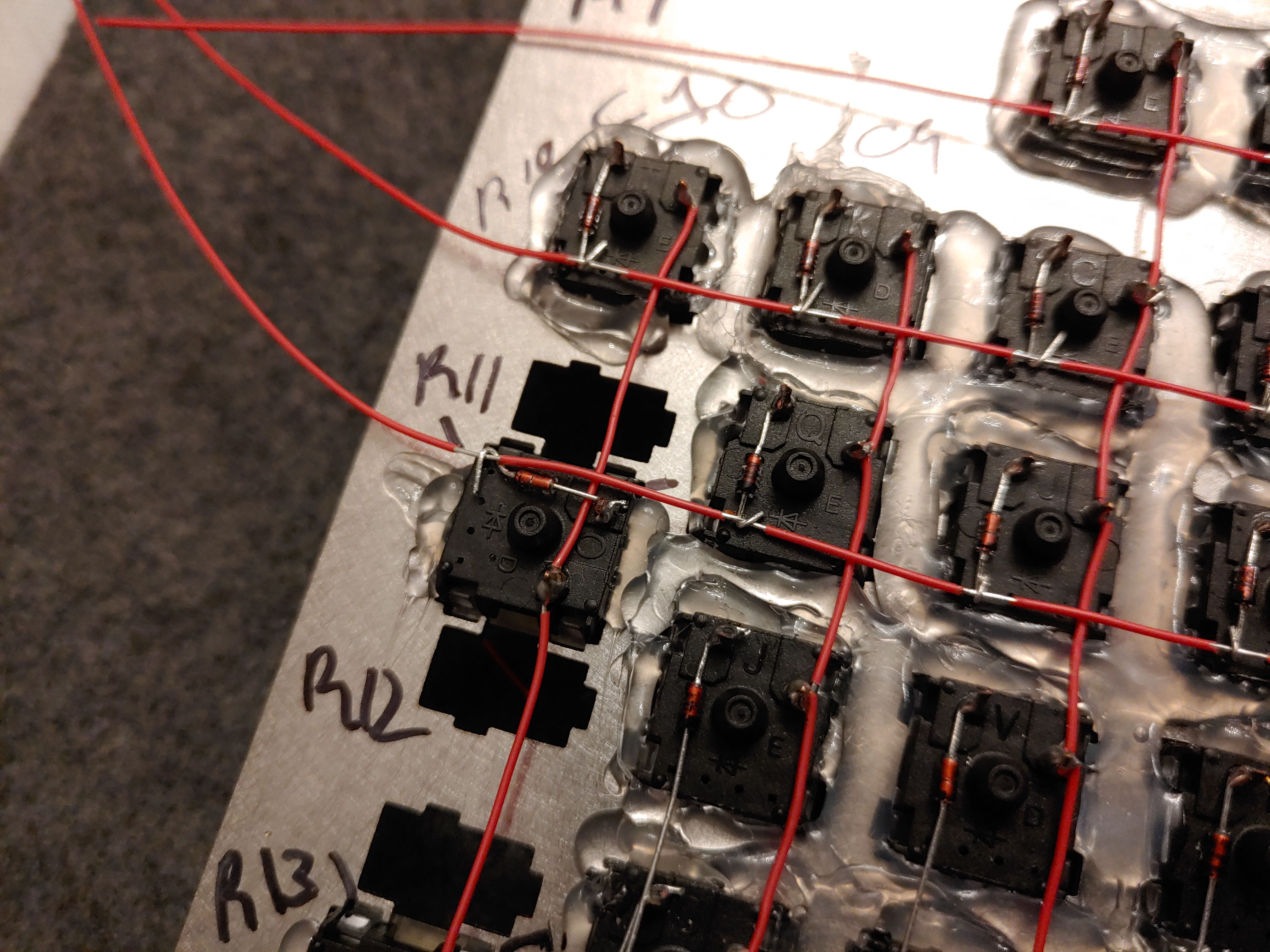
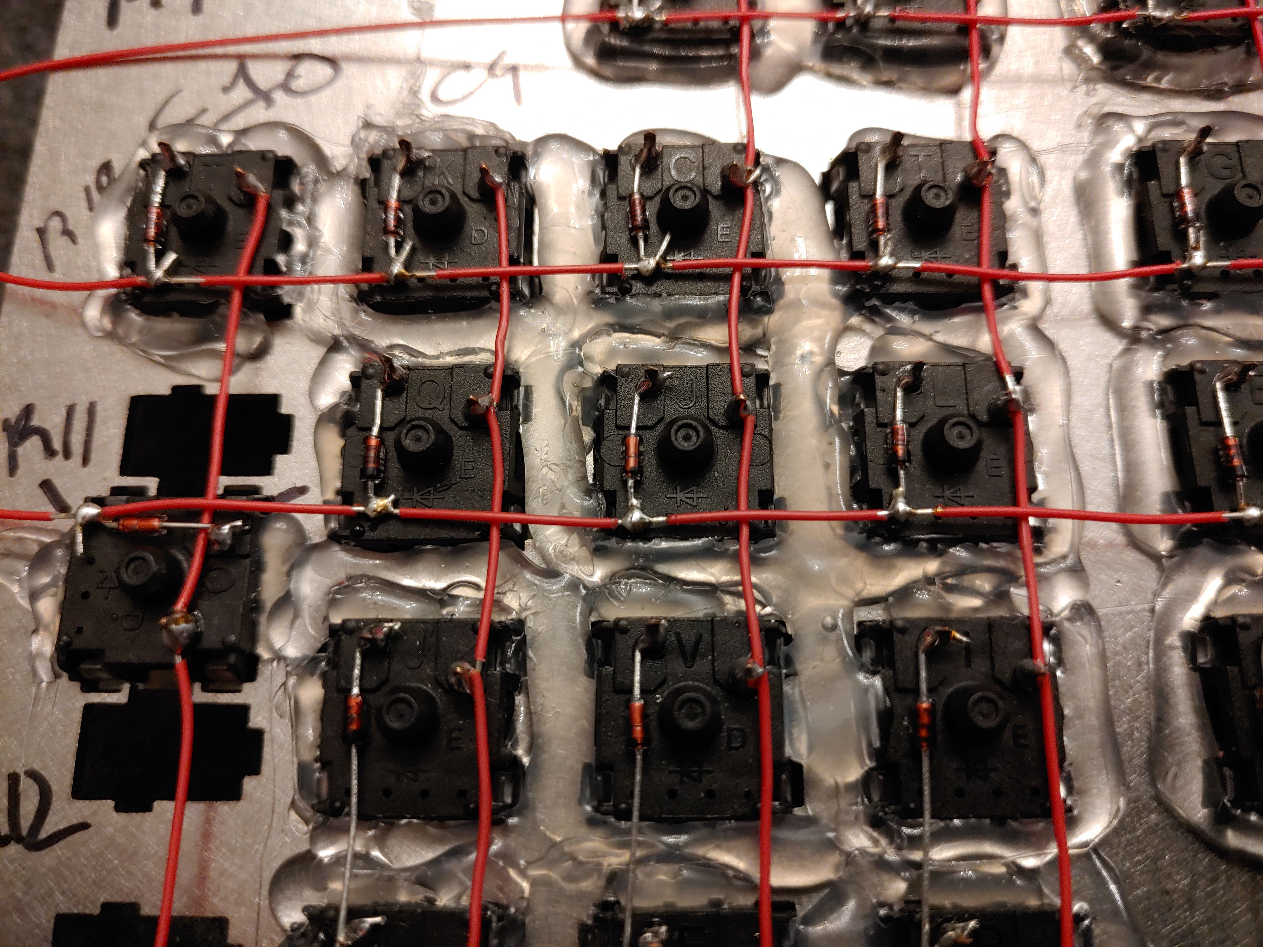
Hot glue crimes against humanity (§)
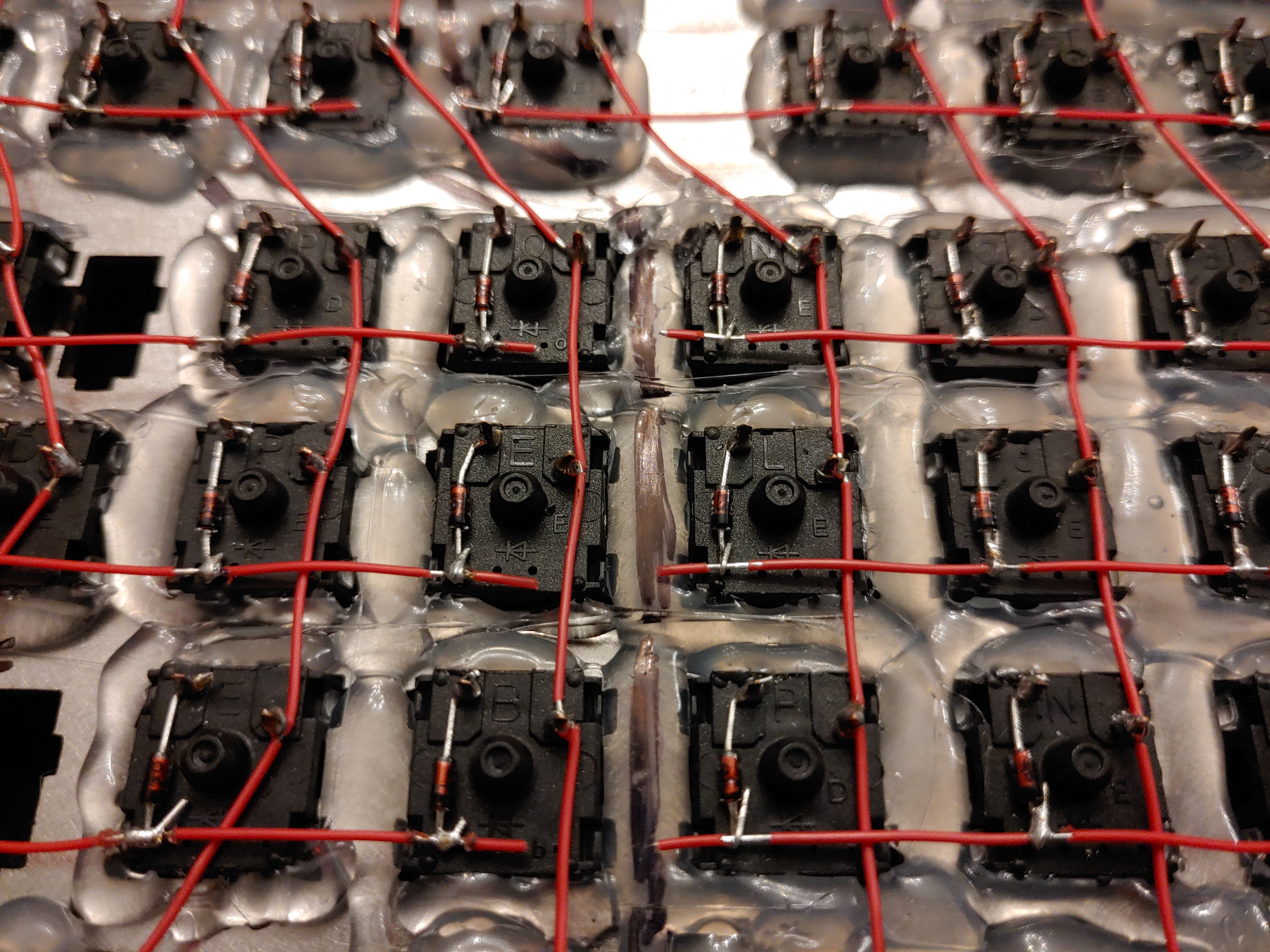
When you press the switches into the plate, they make an audible click. The plastic body of the switch is shaped so that it grips the plate from below. But I couldn't shake the feeling that someday I'd be pulling a cap off of a switch and have the whole switch rip out of the plate, bringing a spaghetti dish of wires along with it. As fun as it was to put this together, I really, really don't want to have to do any repairs. I decided, for better or worse, to reinforce the switches with a whole bunch of hot glue.
WARNING: You're supposed to put your stabilizers in the plate before your switches! My stabilizers were in transit for more than a month by this point, so I just went ahead without them. I was able to add them retroactively but it wasn't ideal. See #Stabilizers.
Speaking of firsts, this was my first time working with hot glue. It's interesting stuff. I think if you use it once you'll either instantly hate it for its awful, stringy messiness; or you'll instantly love it for its versatility and speed.
In the following photos, you should be able to identify three distinct stages of how it went:
- I'm doing terrible at this.
- I'm doing great at this!!
- I need to do a little less great or I'm going to run out of hot glue.
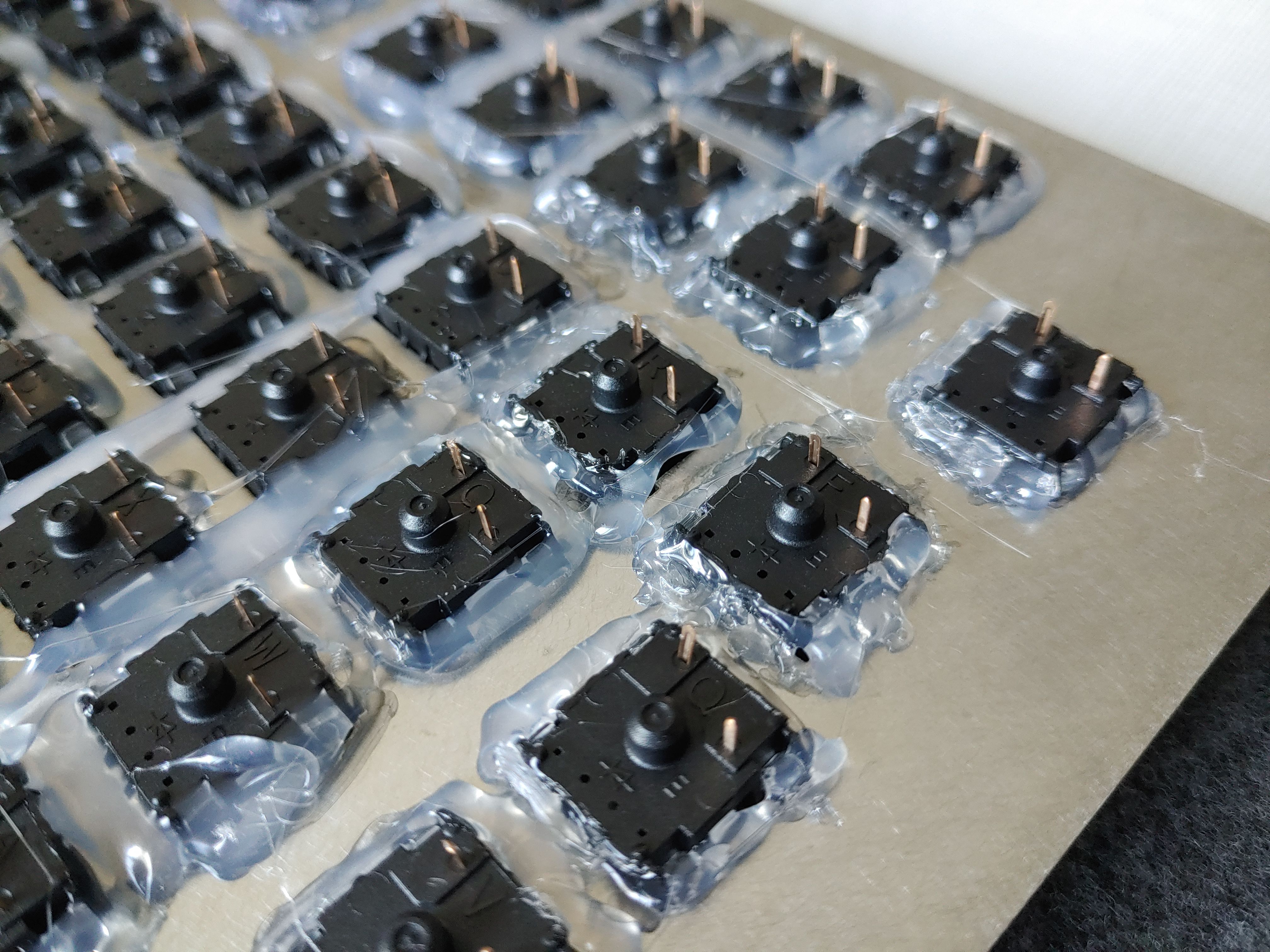
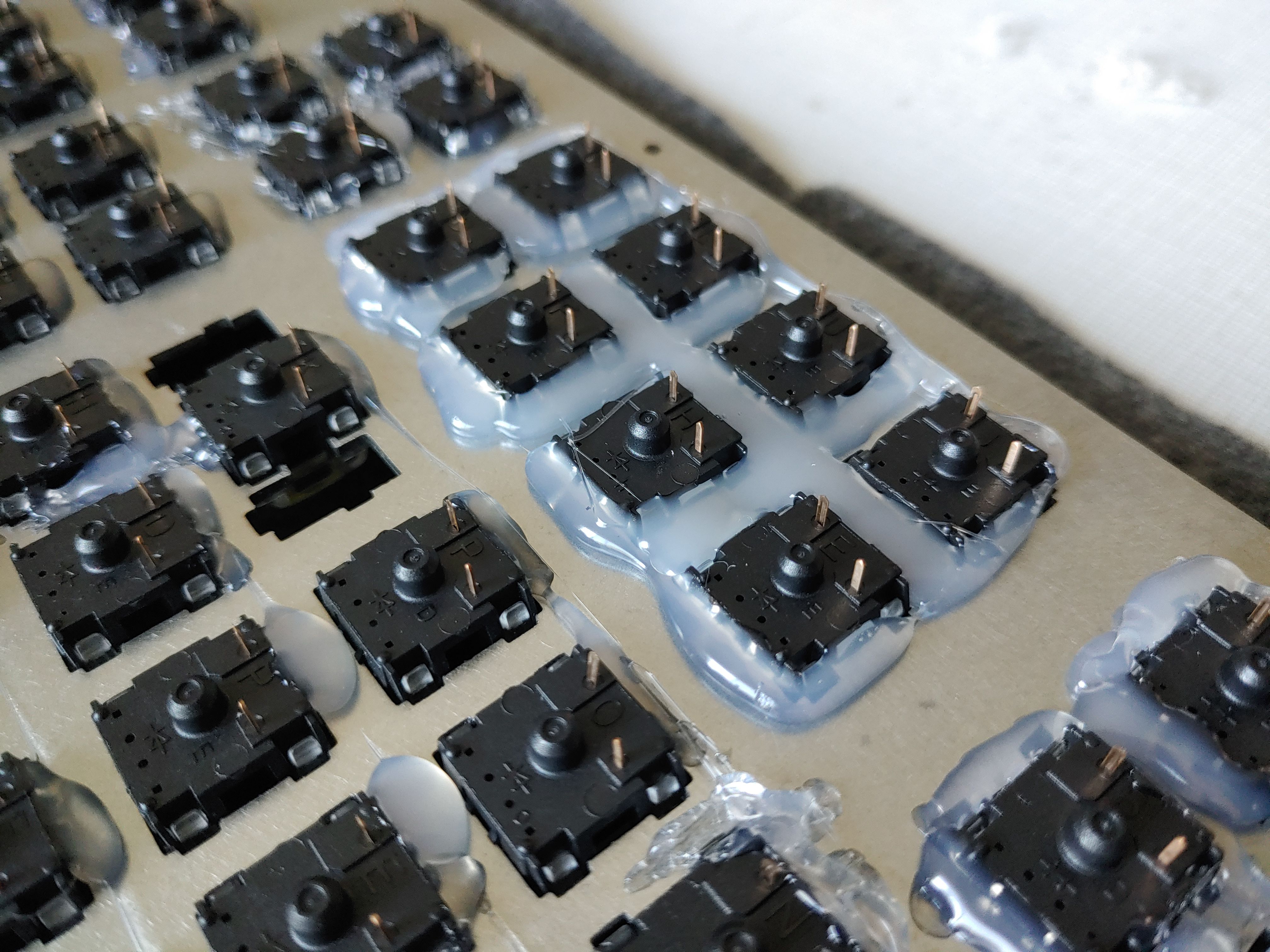
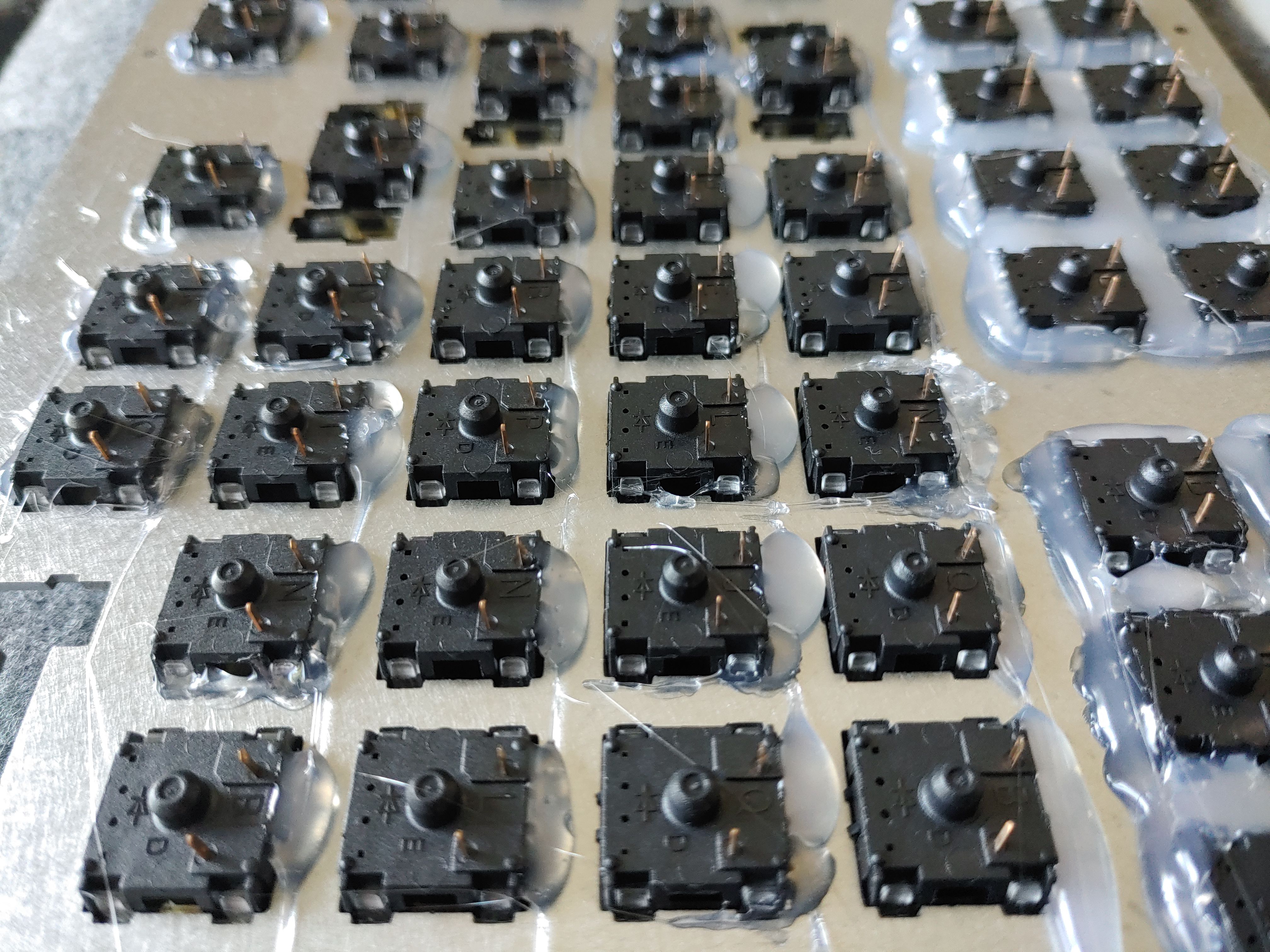

I ran out of hot glue. But, this dark period of my life was short-lived. I bought more glue and got back to work making angels cry:
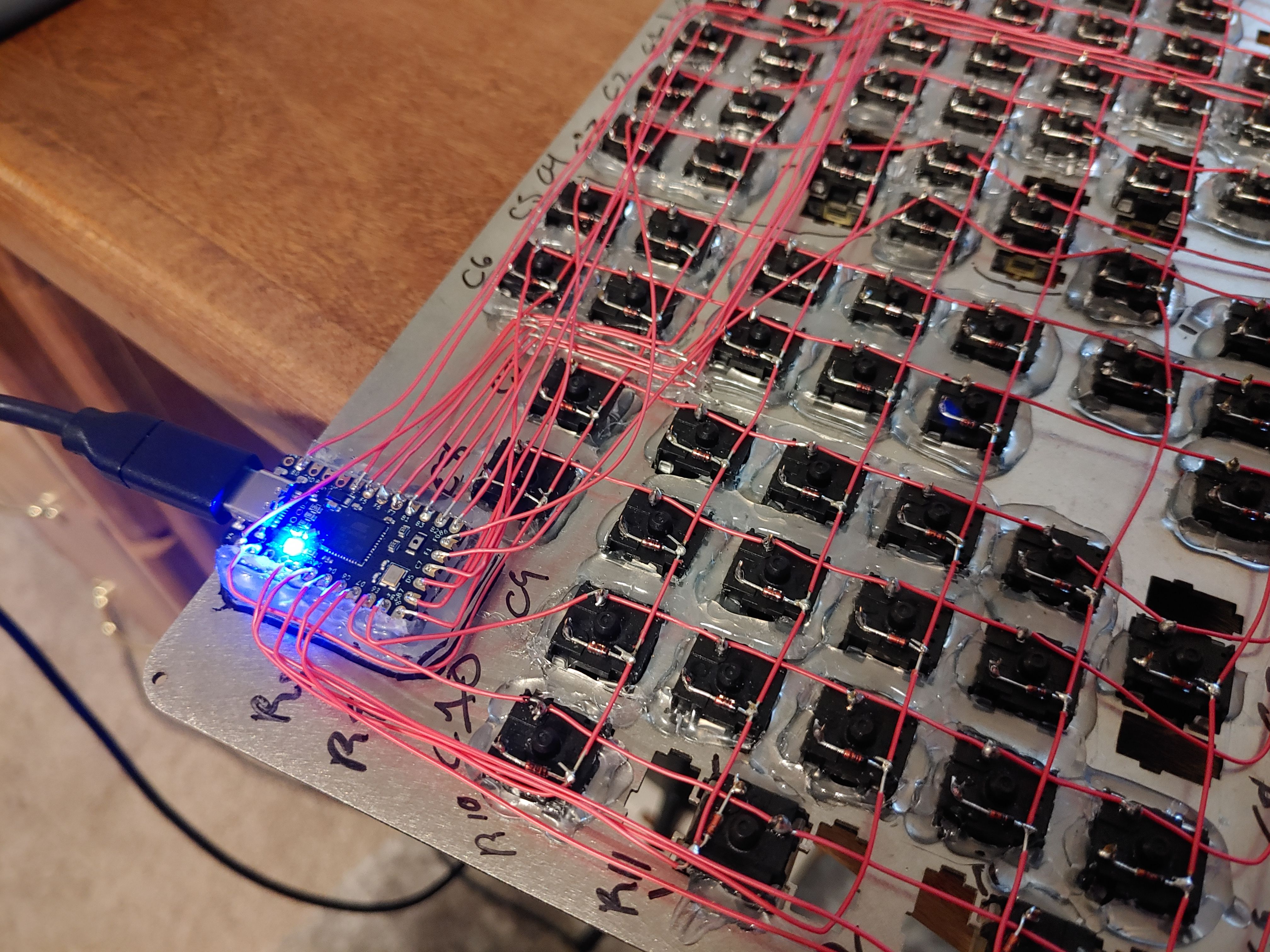
Wiring (§)
Finally, with the plate ready and switches set, it was time to begin wiring.
Columns (§)
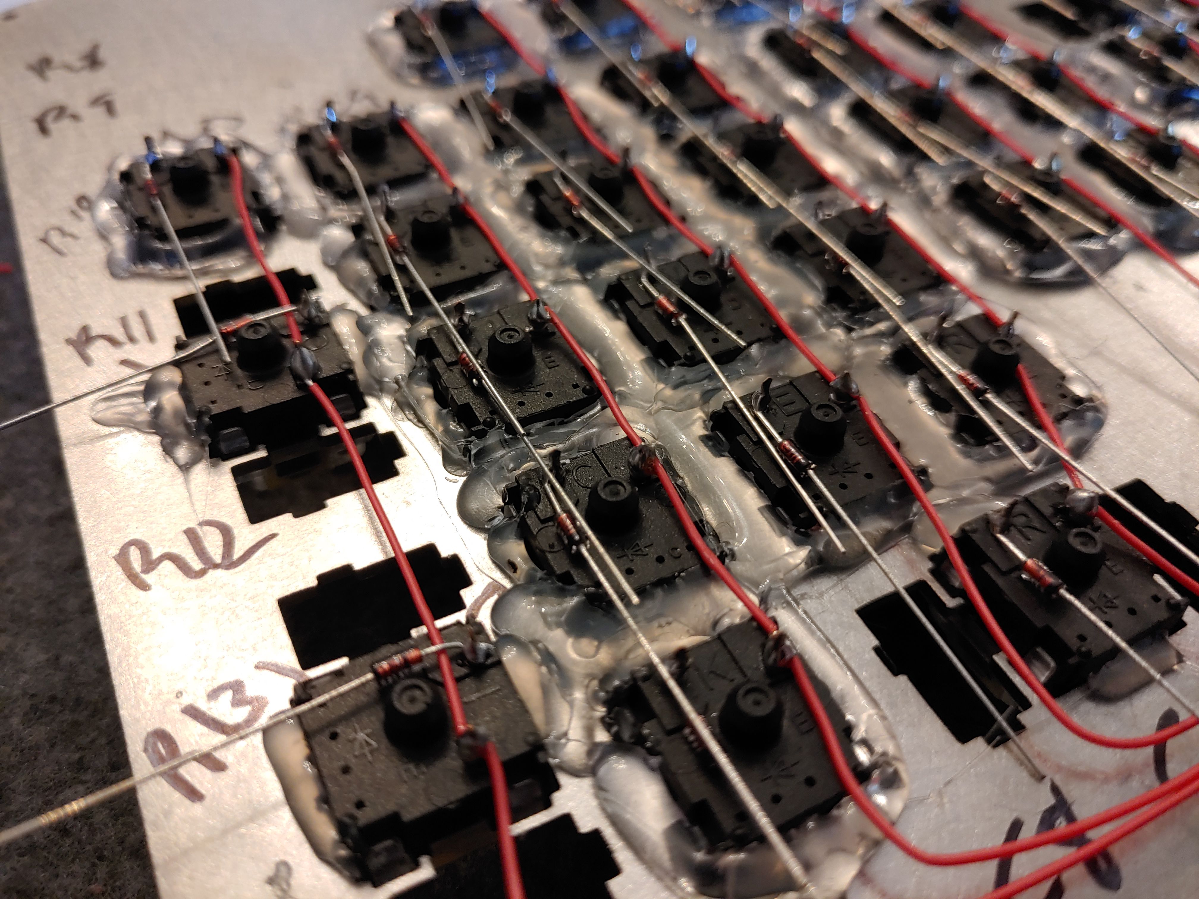
I began with the columns. I was hoping I could use a single strand of wire to connect the whole column, stripping off little gaps in the wire near the posts for soldering, but at this time I couldn't figure out a good way to do that. So, the linkage between each switch was done individually. I wound a bit of wire around each post, and in fact did a dry fit of the whole board before soldering anything.
This took a long time.
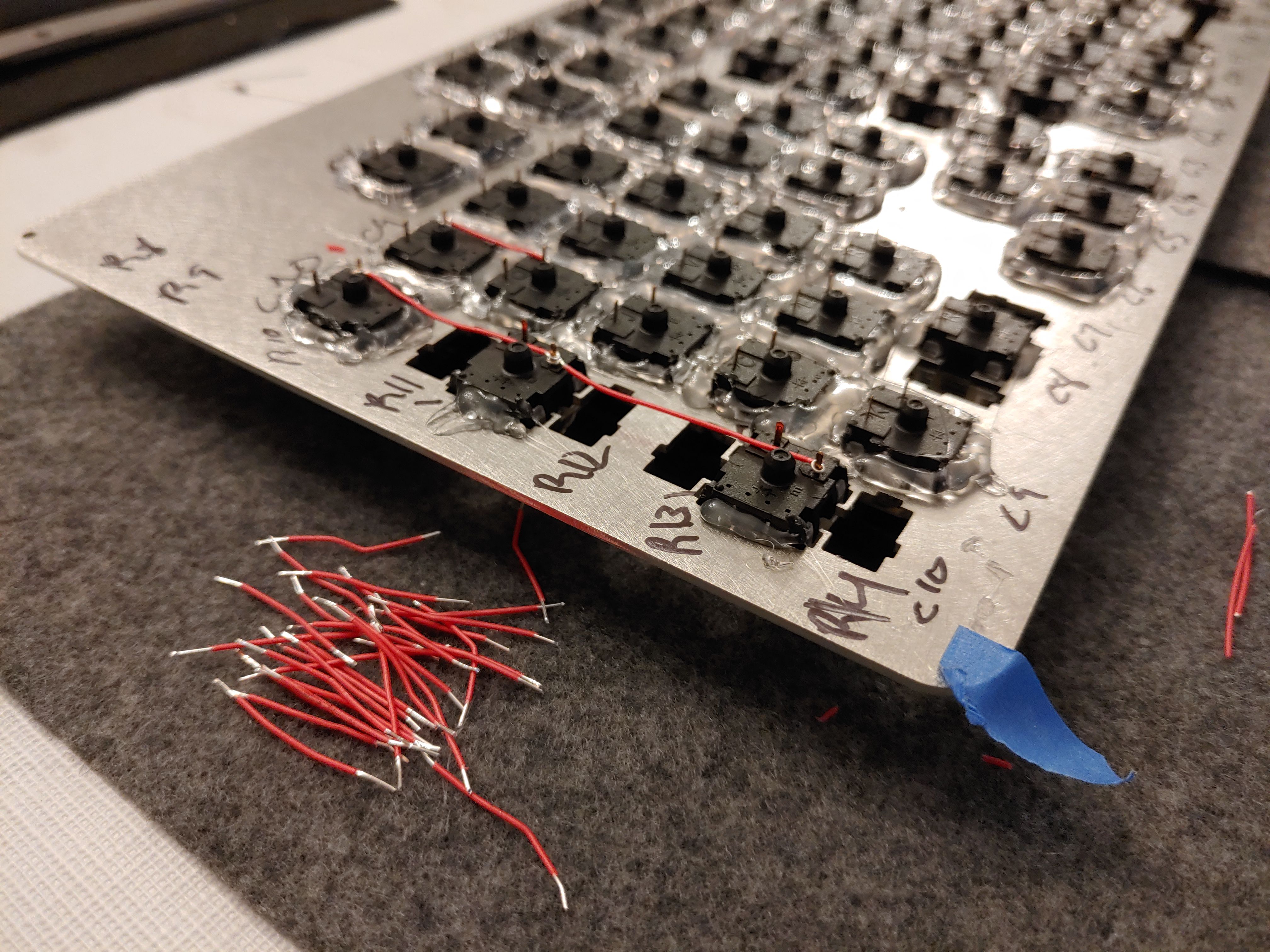


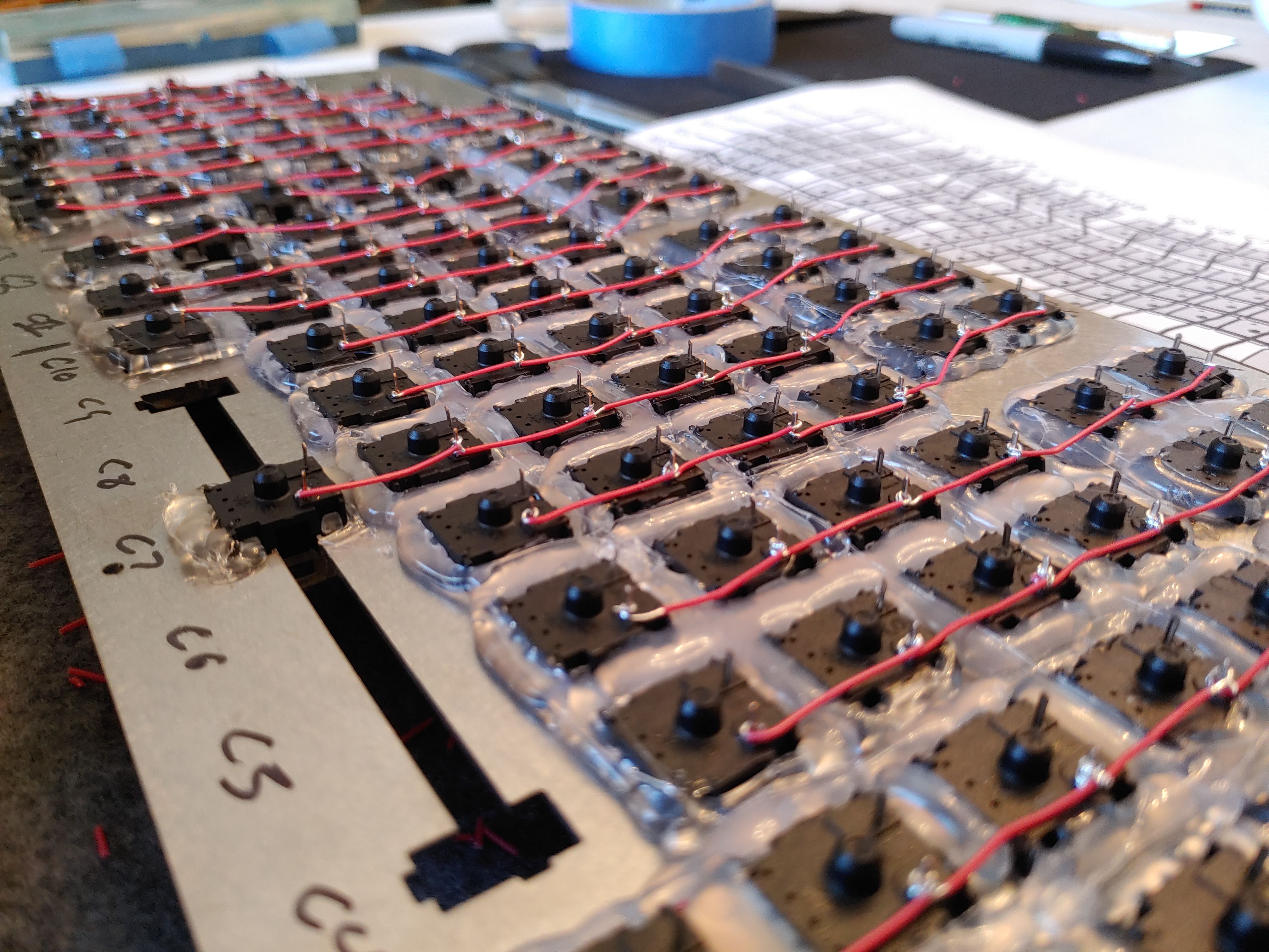
I linked the duplexed columns, and held them down with tape since these long wires tend not to want to sit still.

Then I began soldering. This was my first time soldering, and I think I did pretty alright.

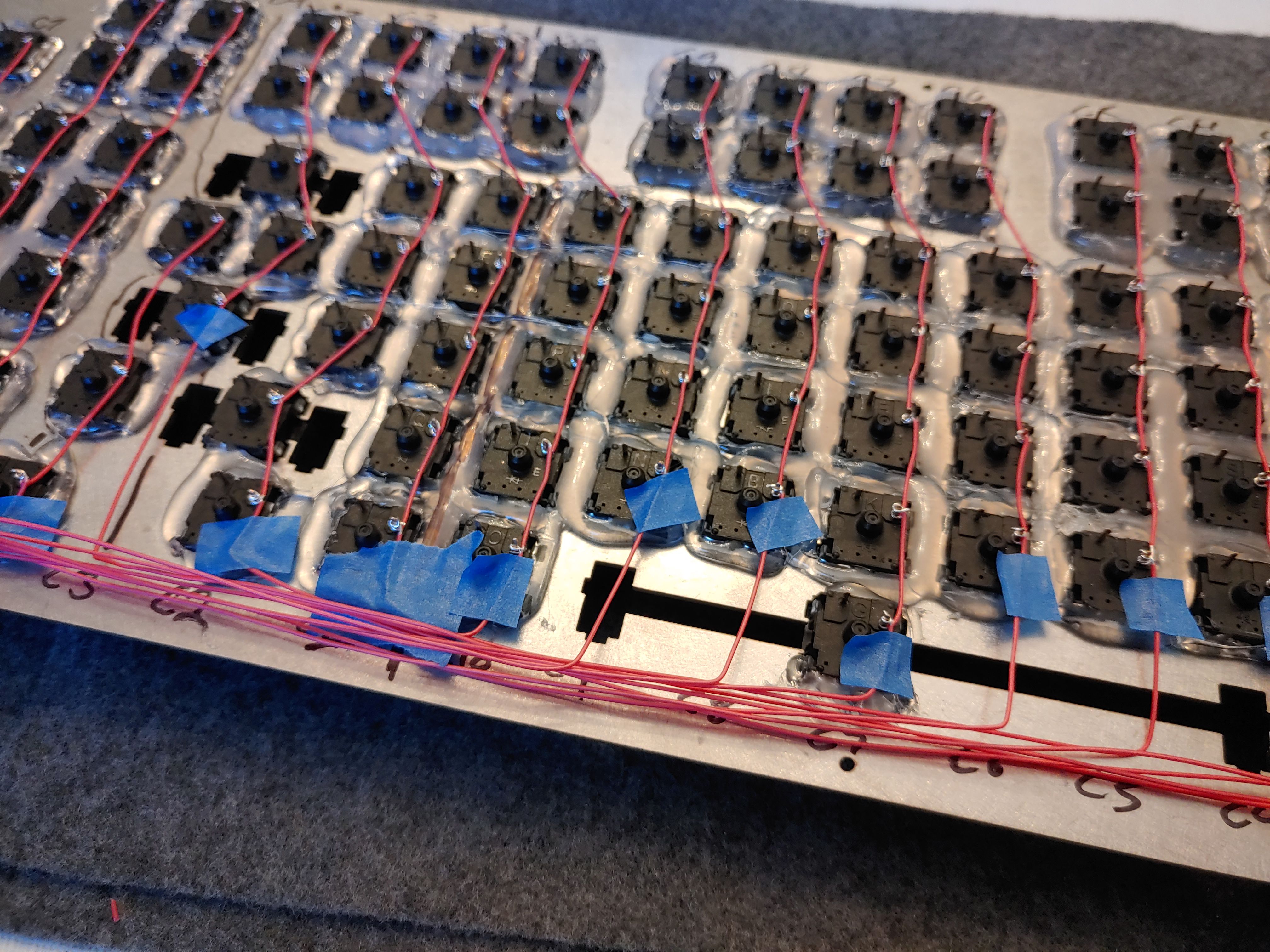
Diodes (§)
Next, I did the diodes. As you can see from the diagram, the diodes are soldered to the other post and reach down to the row wire. The black ring around the diode indicates the front, and should point away from the switch towards the row wire.
I found that using the plate itself as a bending guide for the diode tails was perfect for helping me wrap them around the posts.

Unlike the column wires, I didn't dry-fit the whole board, because the other tail of each diode reaches down to the next one. So, I did dry fits and solders for each row, bottom to top.
This took a long time.

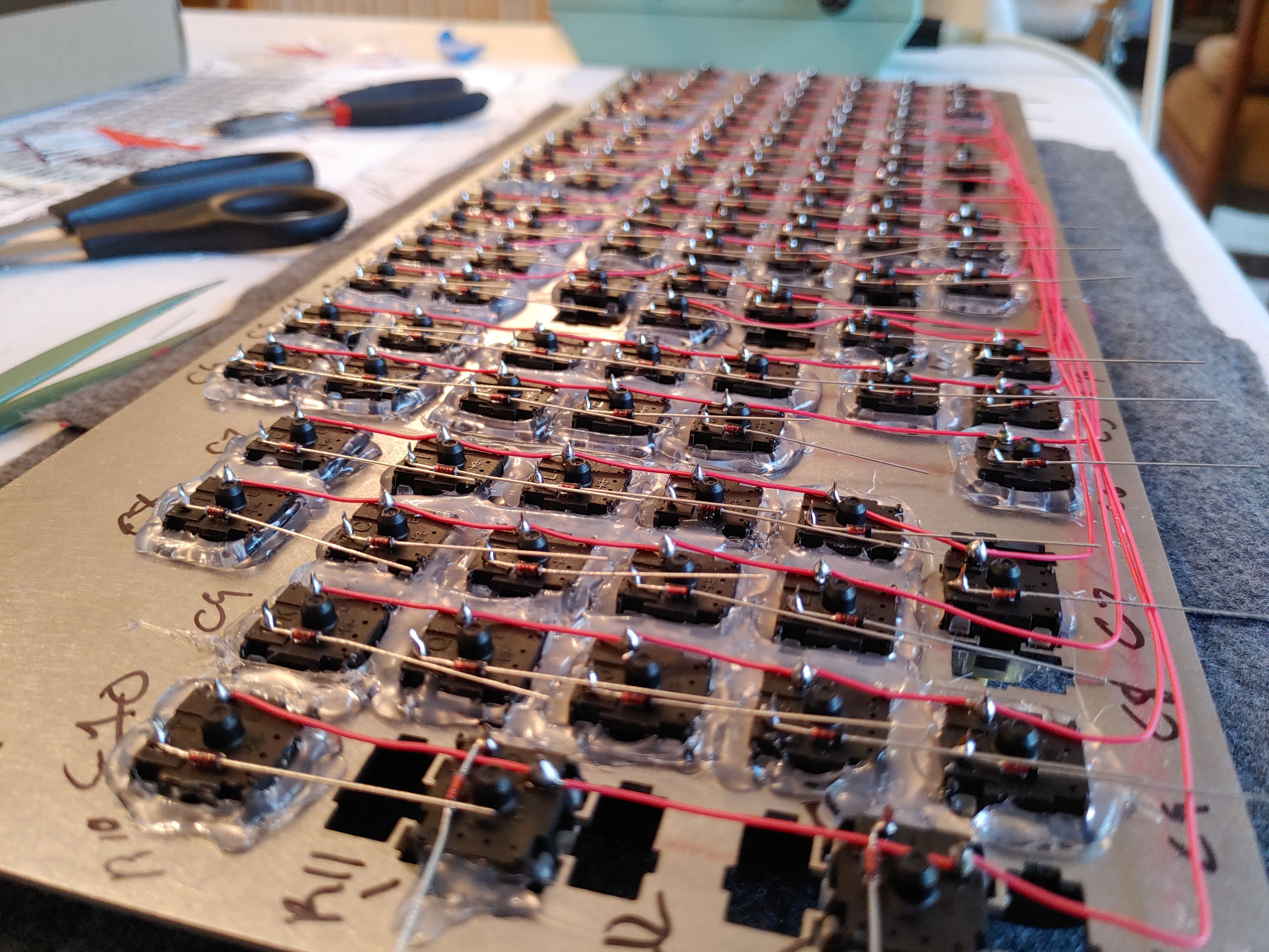
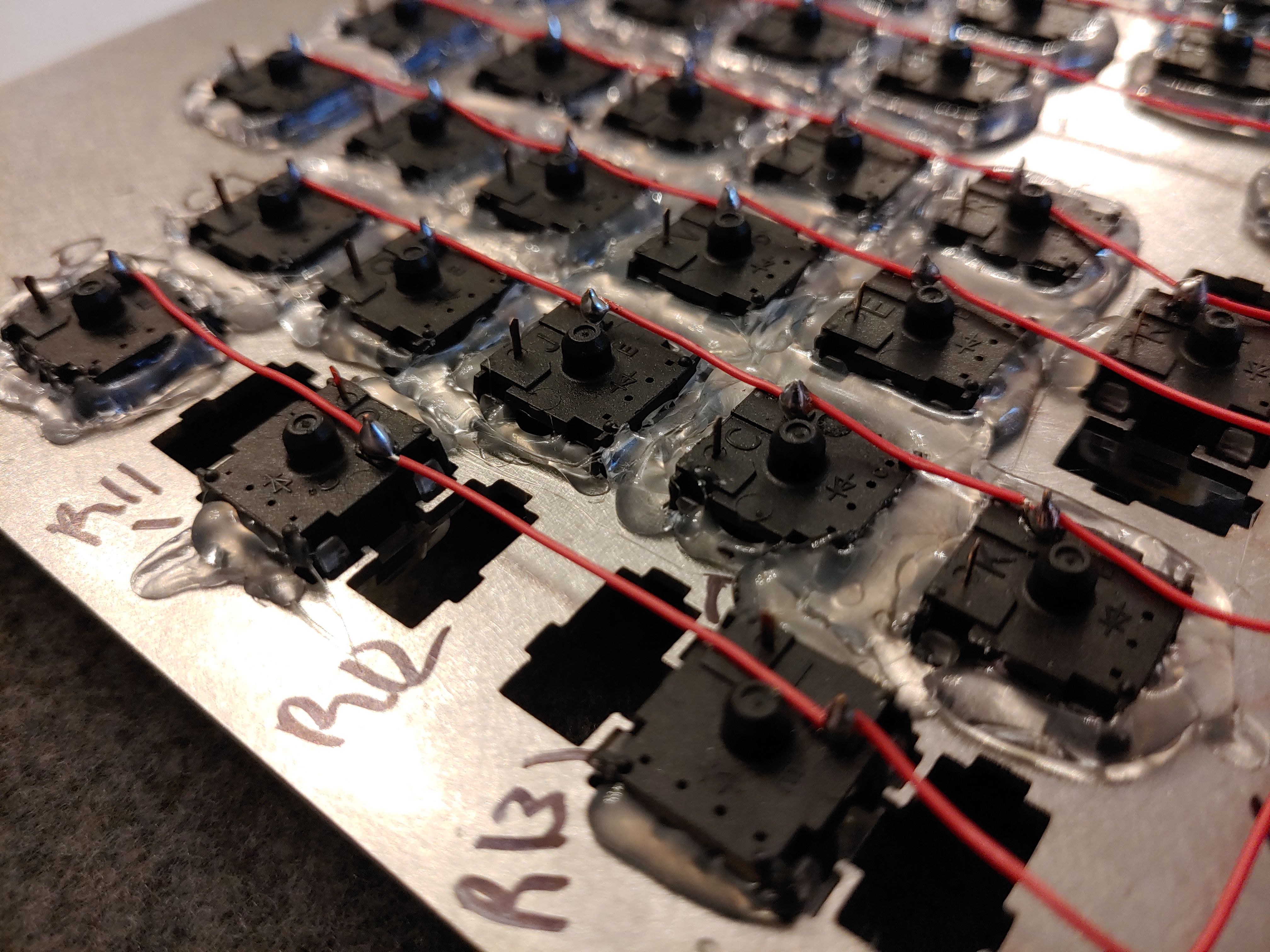
Rows (§)
Next up was the rows. Remember how I wanted to strip the middles of the wires when I was doing the columns? Well now I was extra motivated to find a solution, because doing individual wires for the rows would mean three-way joins between each row segment and the accompanying diode, and I didn't want to deal with that.
I found that I could use the soldering iron to melt away the insulation from the wire. This was very effective, but in retrospect was a BAD IDEA because it made the tip very dirty and difficult to solder with afterwards. More crimes against humanity. Sorry. I was able to clean the tip by repeatedly burning solder onto it and wiping it off, which burned away the rubber residue.
This took a long time.
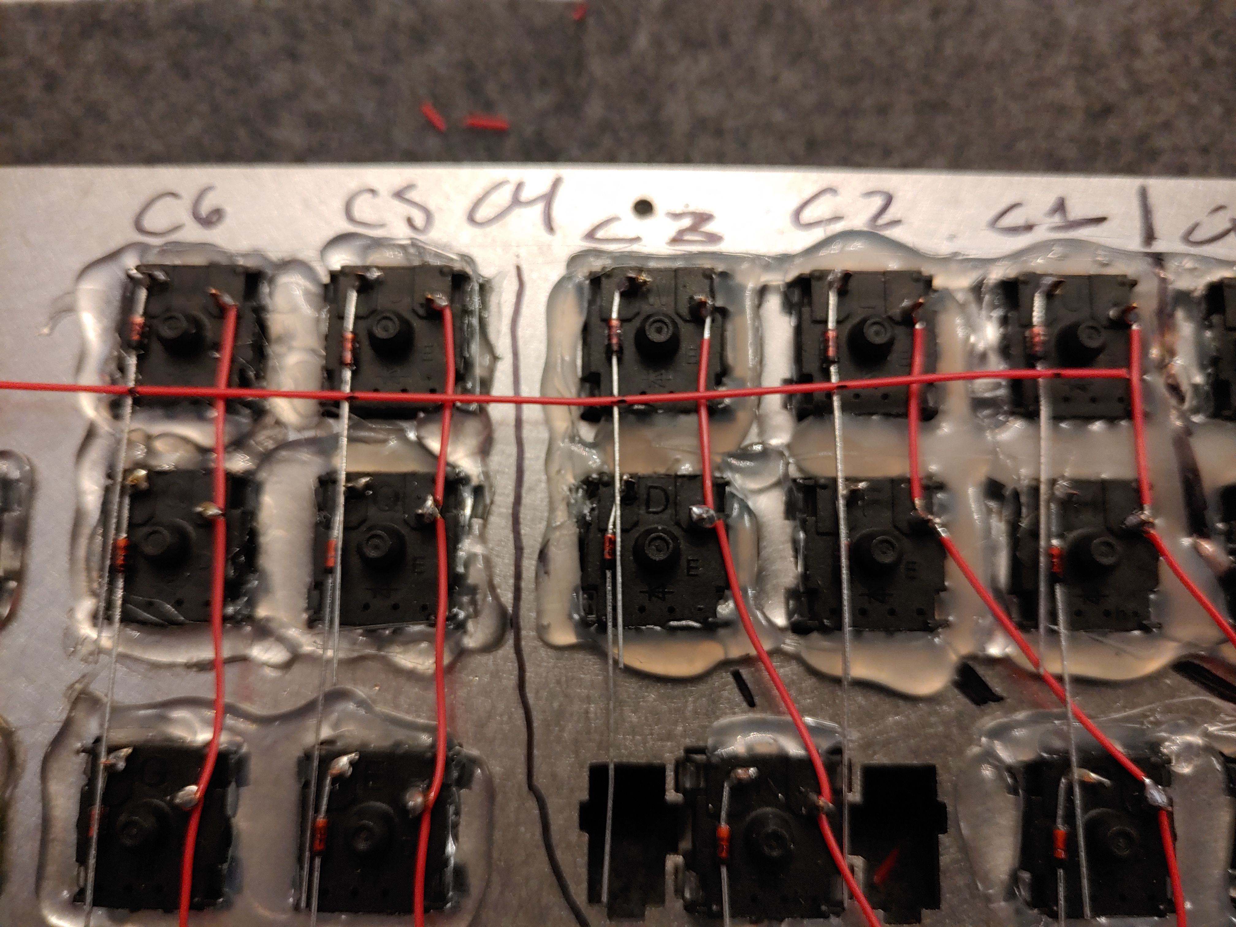
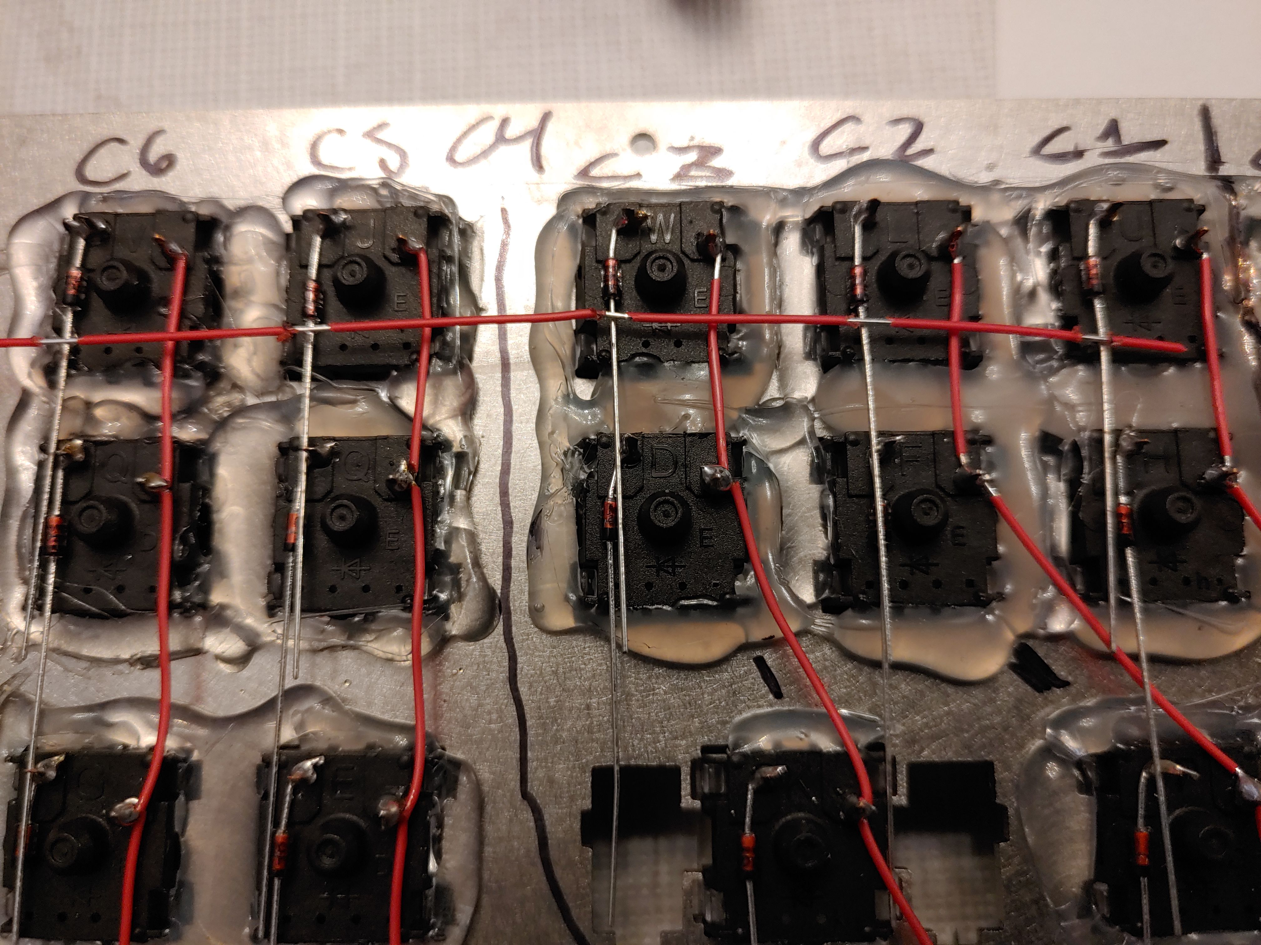
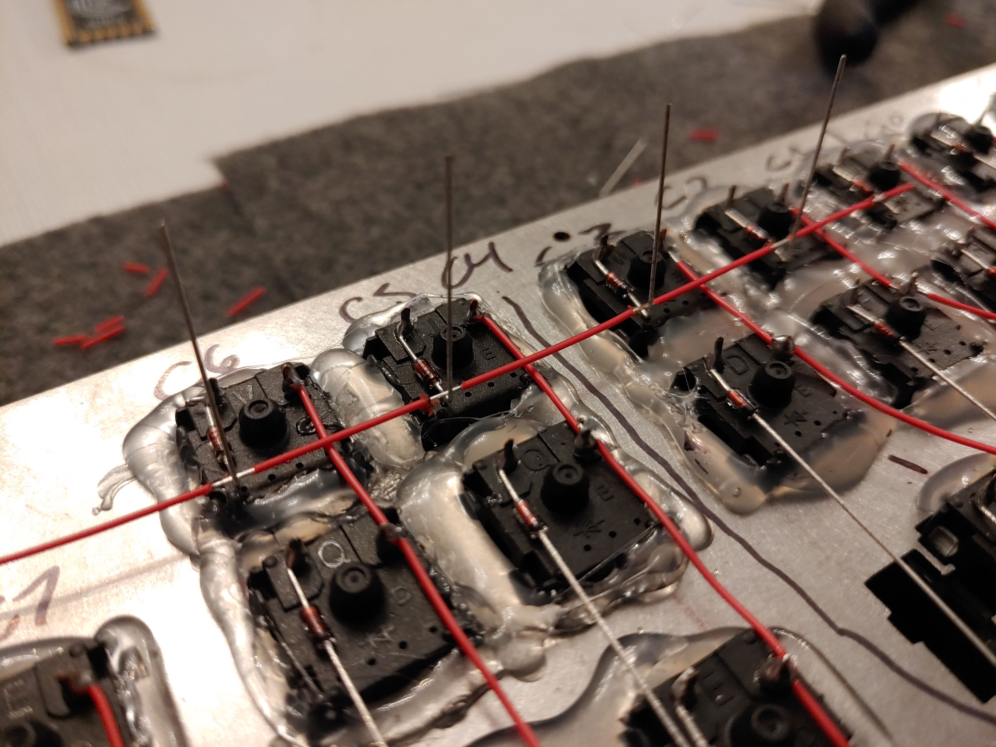
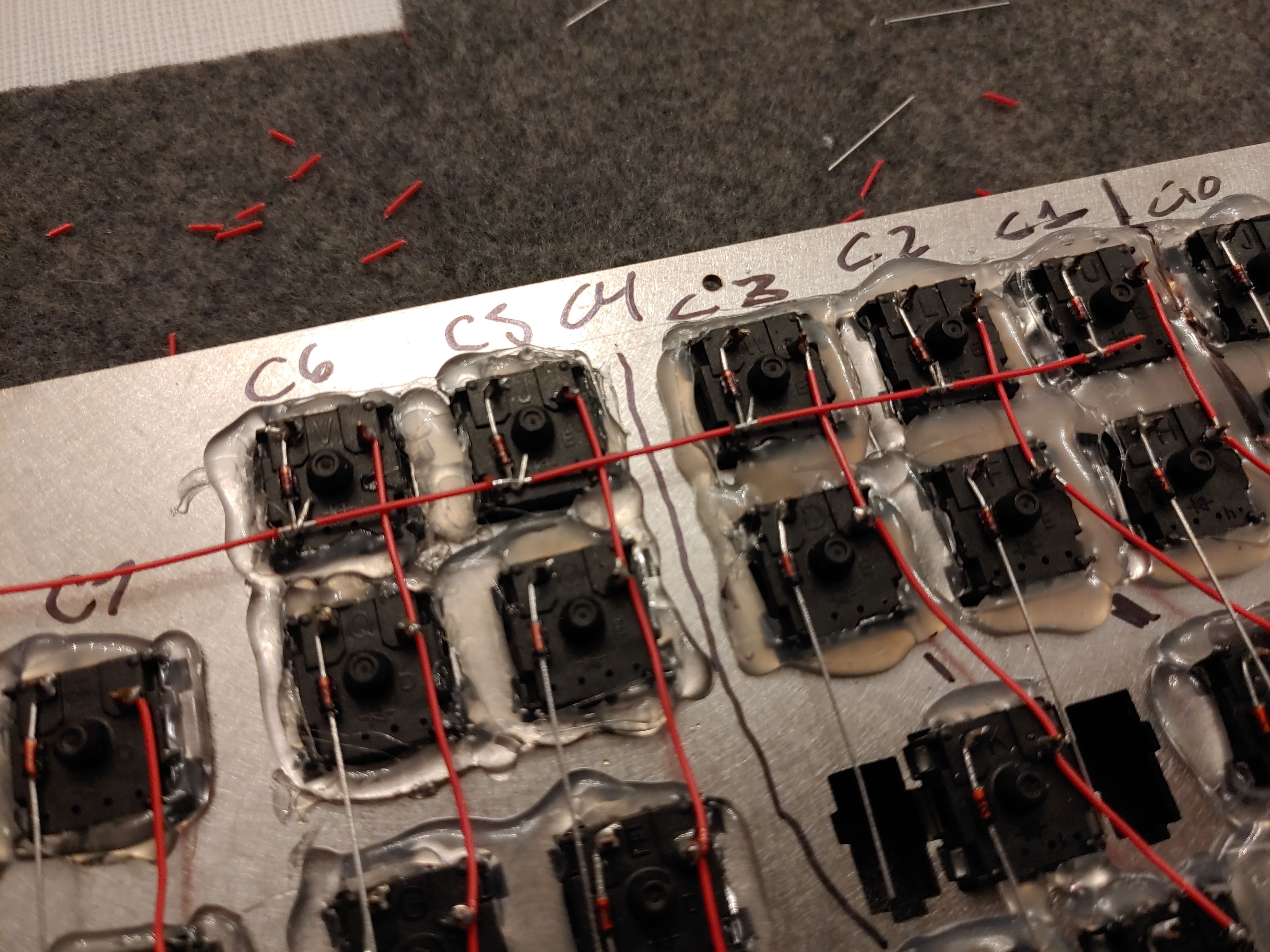
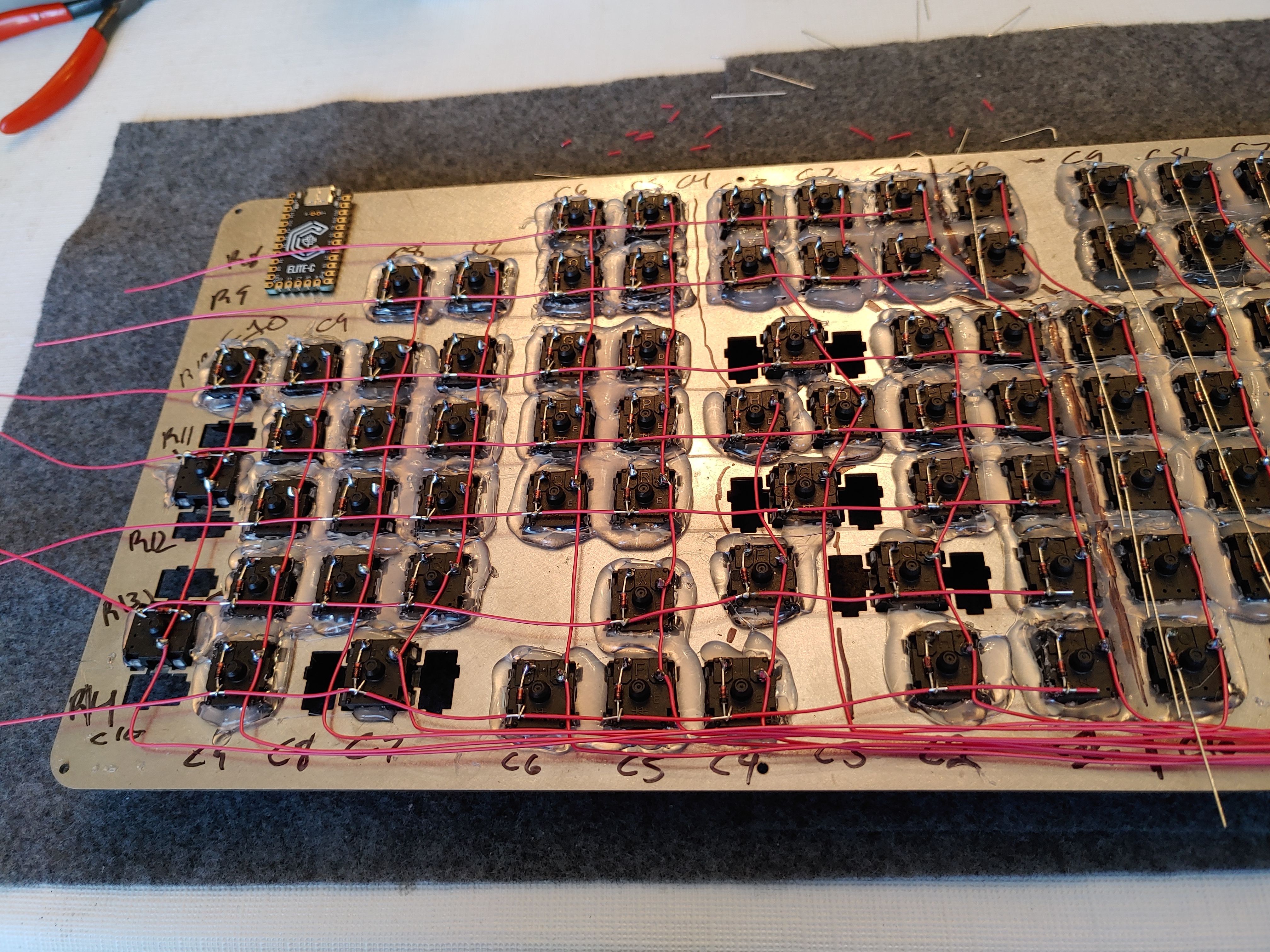
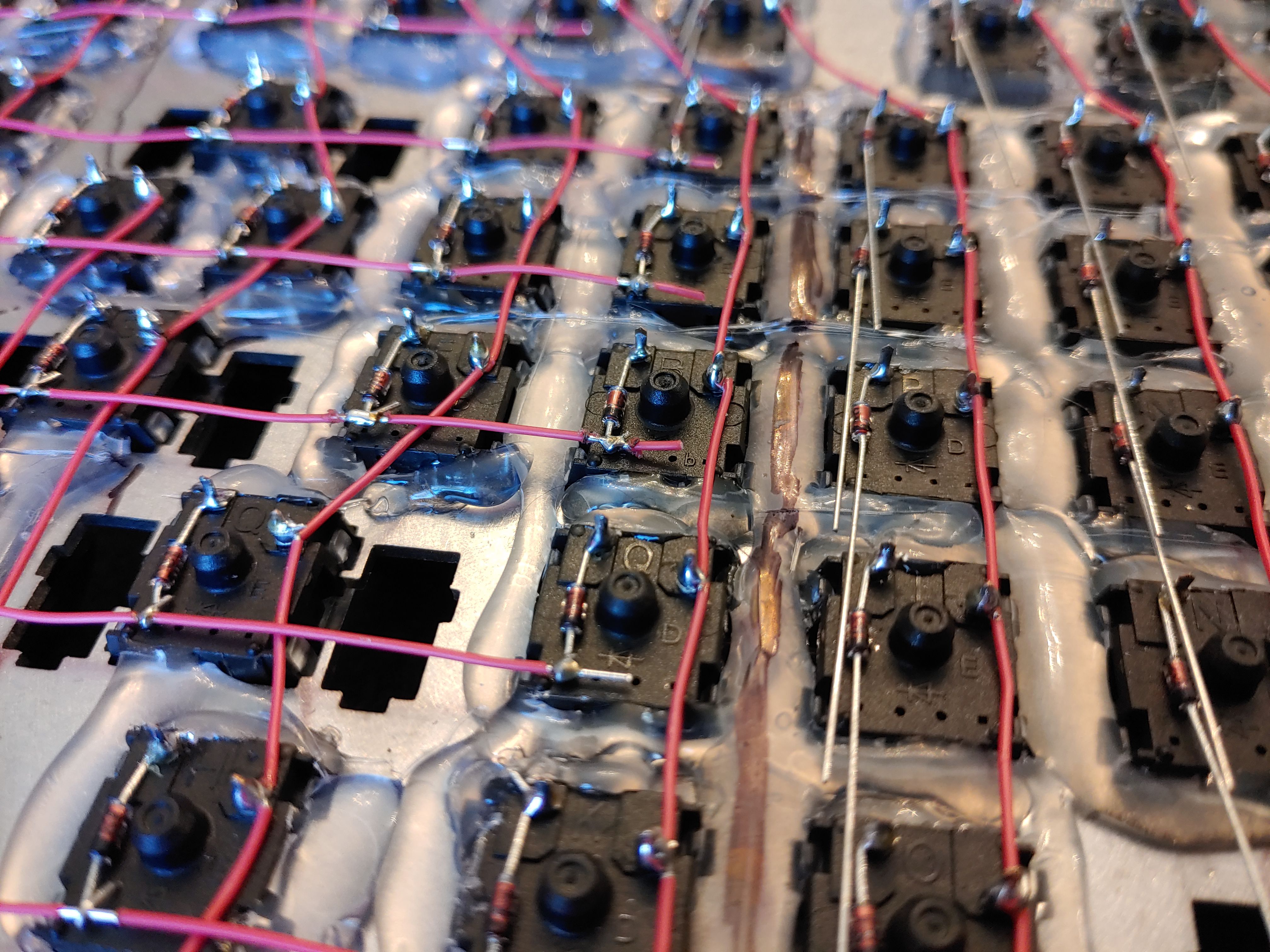
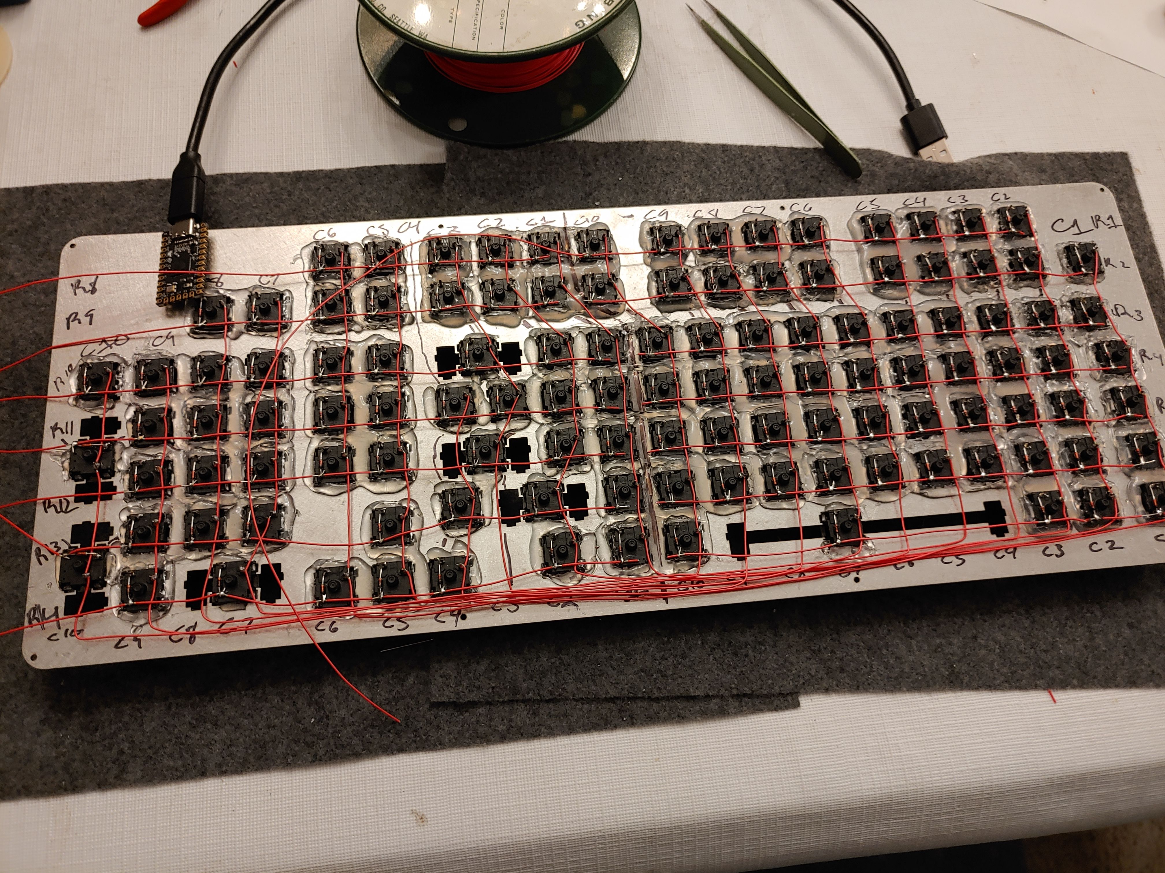
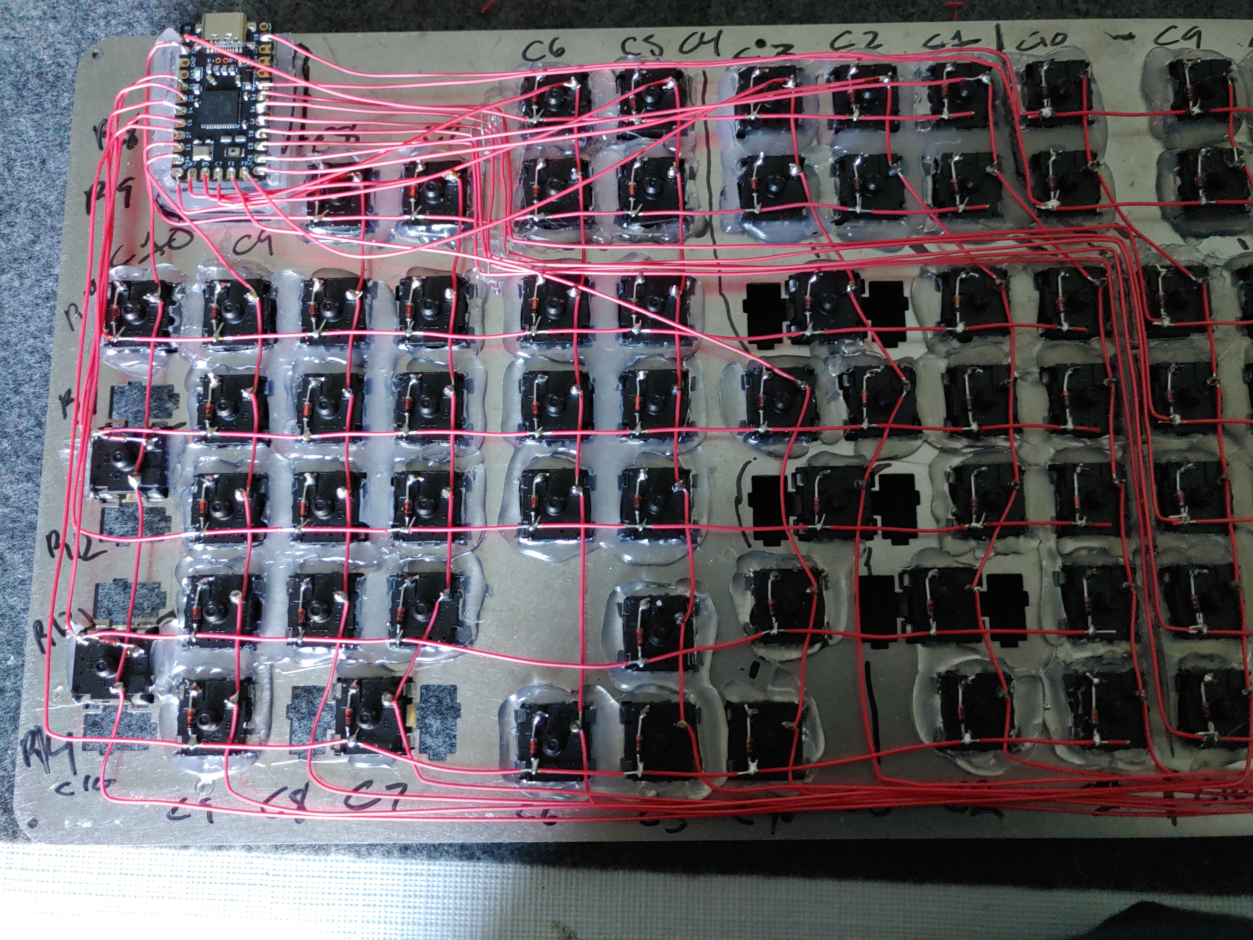
The downside of the duplex layout is that R1-R7 need to reach allll the way over to the controller, so I tried to route the wires between the keys and keep it looking nice.
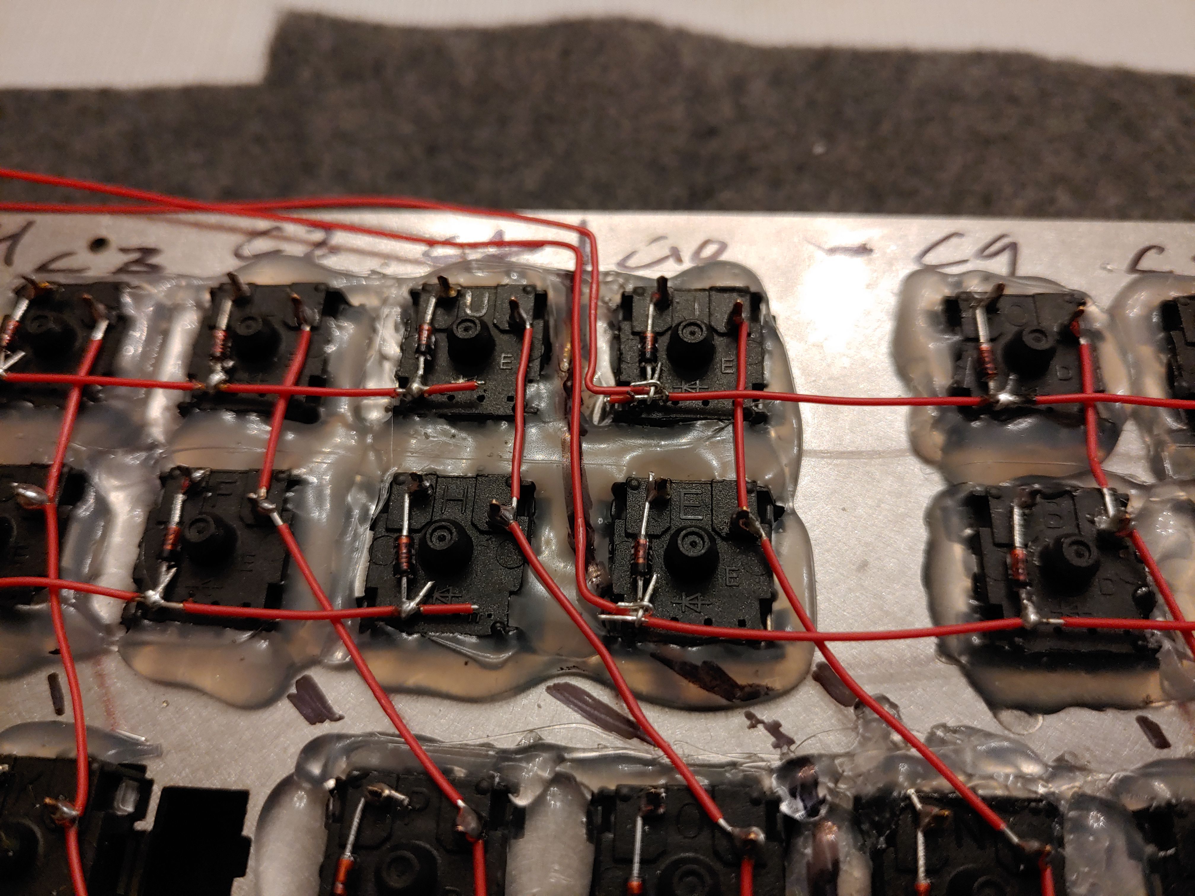
The underlying ocean of hot glue proved its worth by helping me seat some discarded pieces of diode tails, which I used as guides to stop the wires from flying around all over the place. Seriously, it's impossible to totally straighten a wire like this, so they always fling themselves to one side at every chance they get.

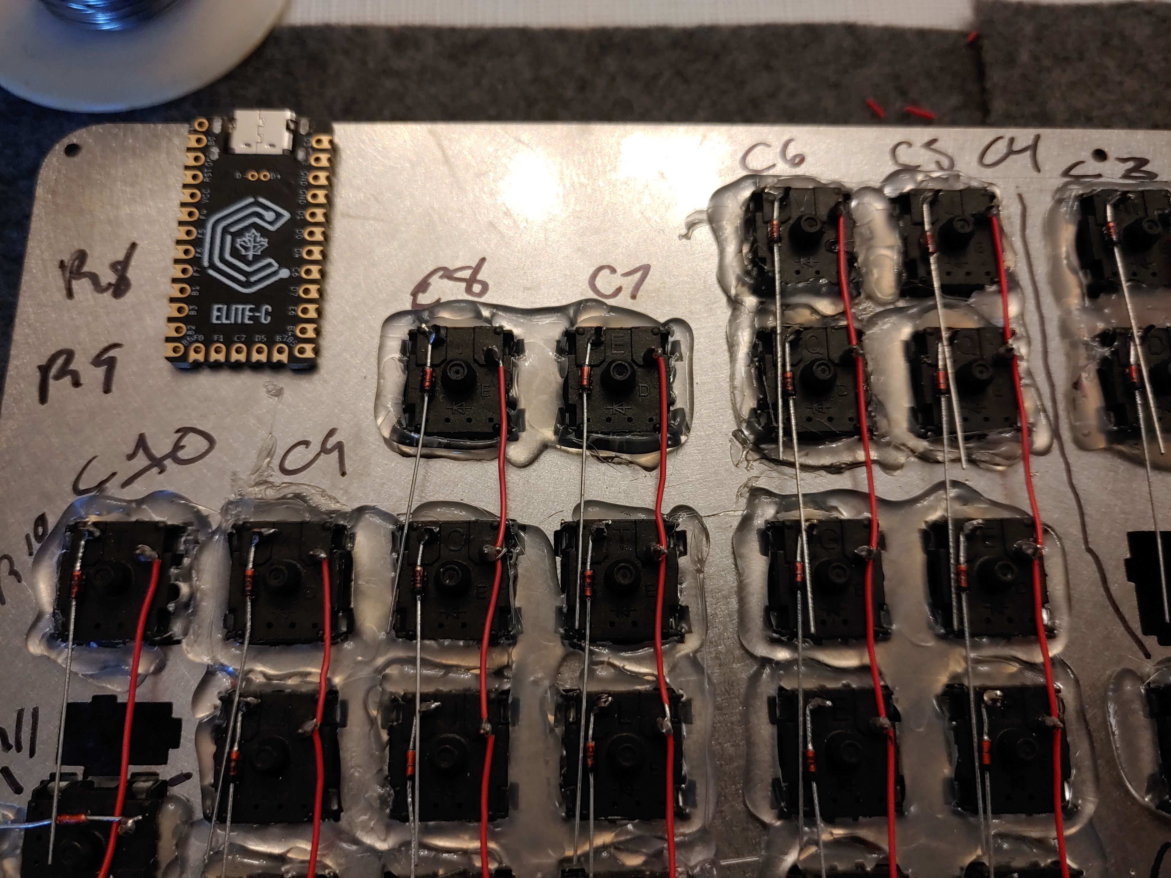
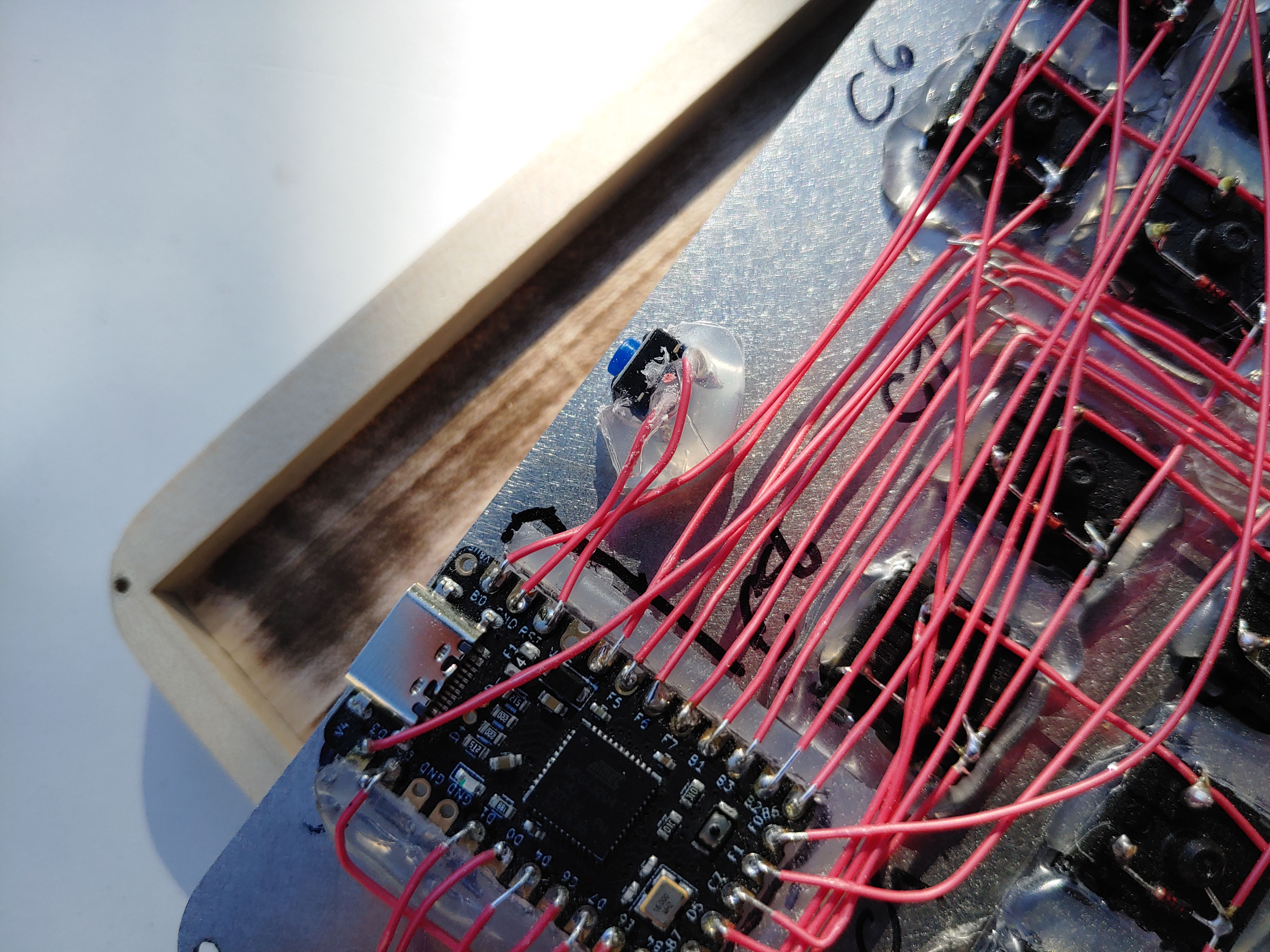
Controller (§)
I hope you're ready for more hot glue crime because I've got more hot glue crime.
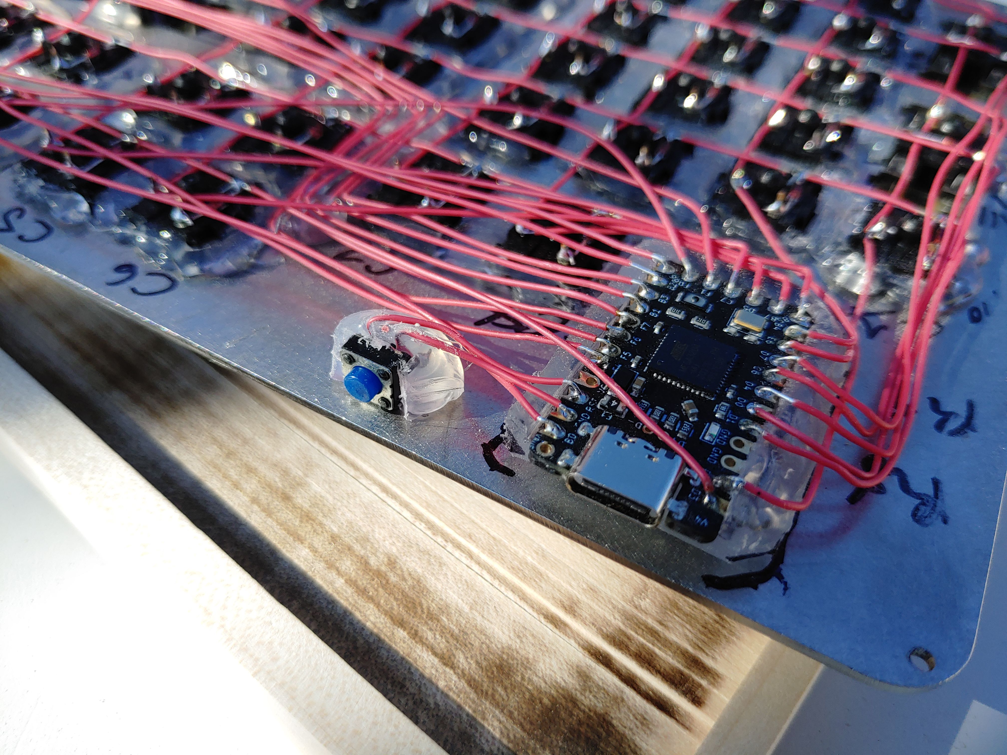
I didn't want to glue the controller directly to the plate for two reasons. First, if for any reason I ever need to remove the controller, I don't want to be prying it off the metal and breaking anything. And second, I want the plug to be approximately centered along the backside of the keyboard base — not pressed directly up against the top. So, I did a little bit of manual 3D printing with everyone's favorite polymer.
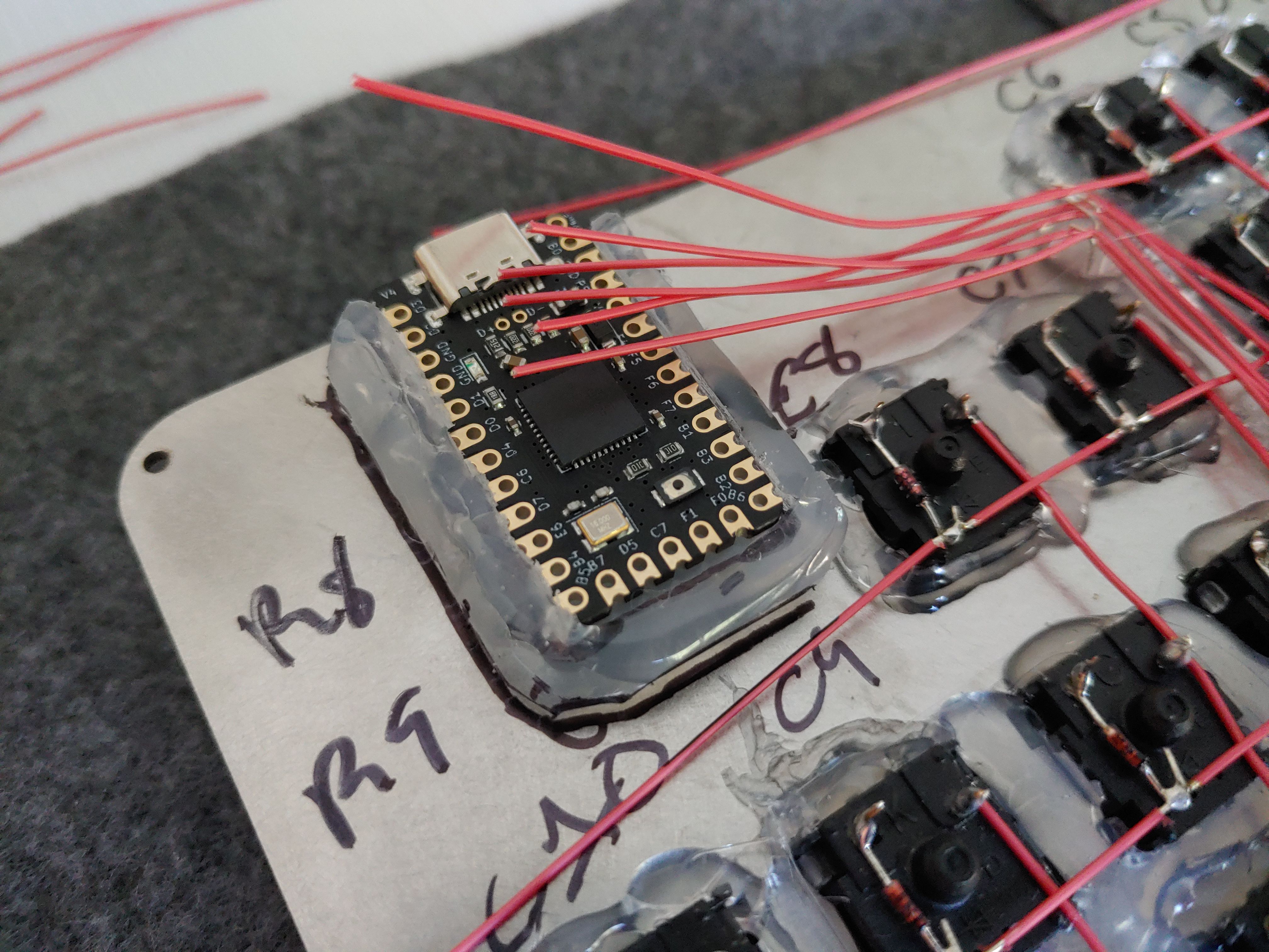
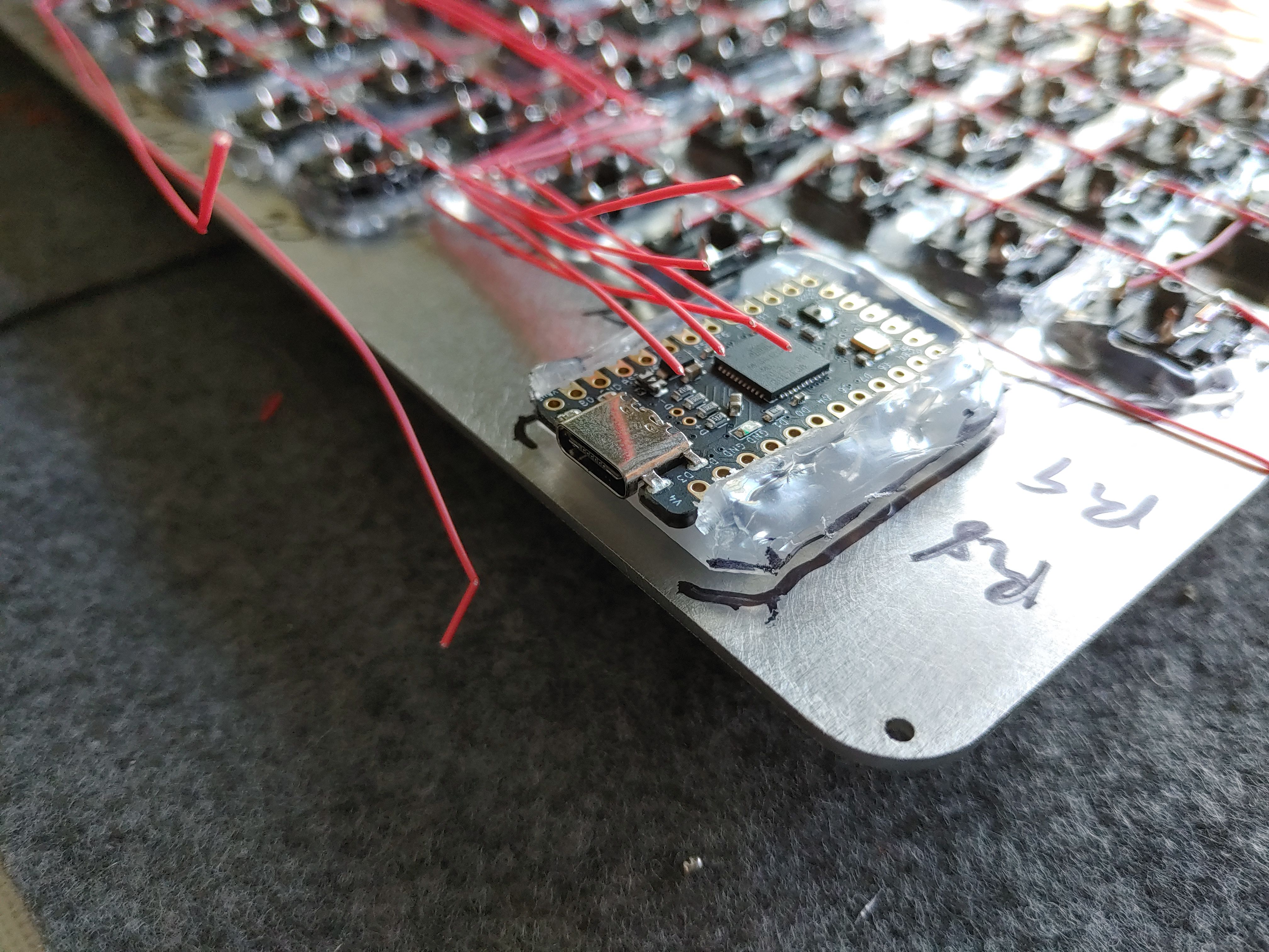
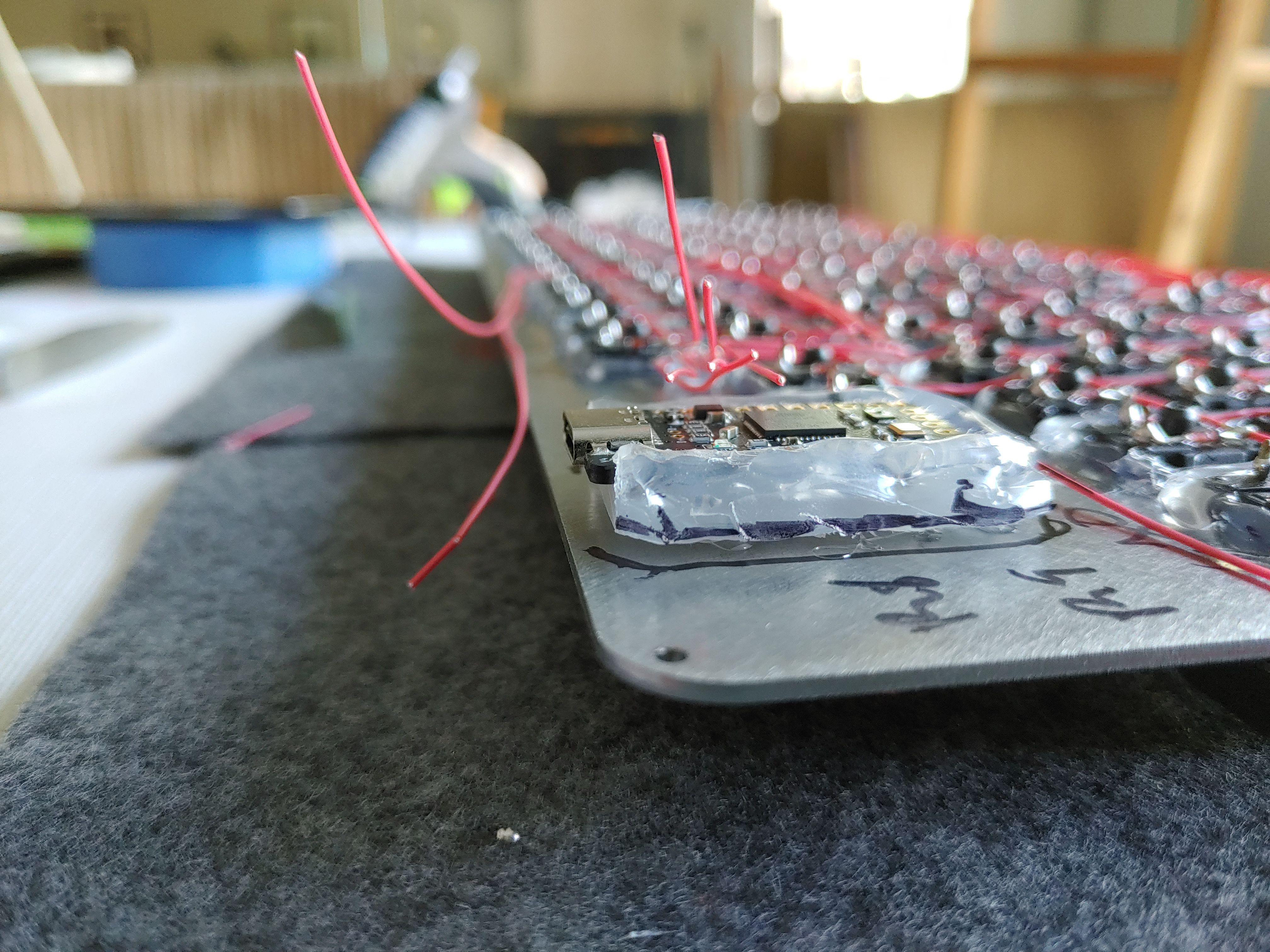
And finally, I could make the last solder joins, from all the rows and columns to the controller.
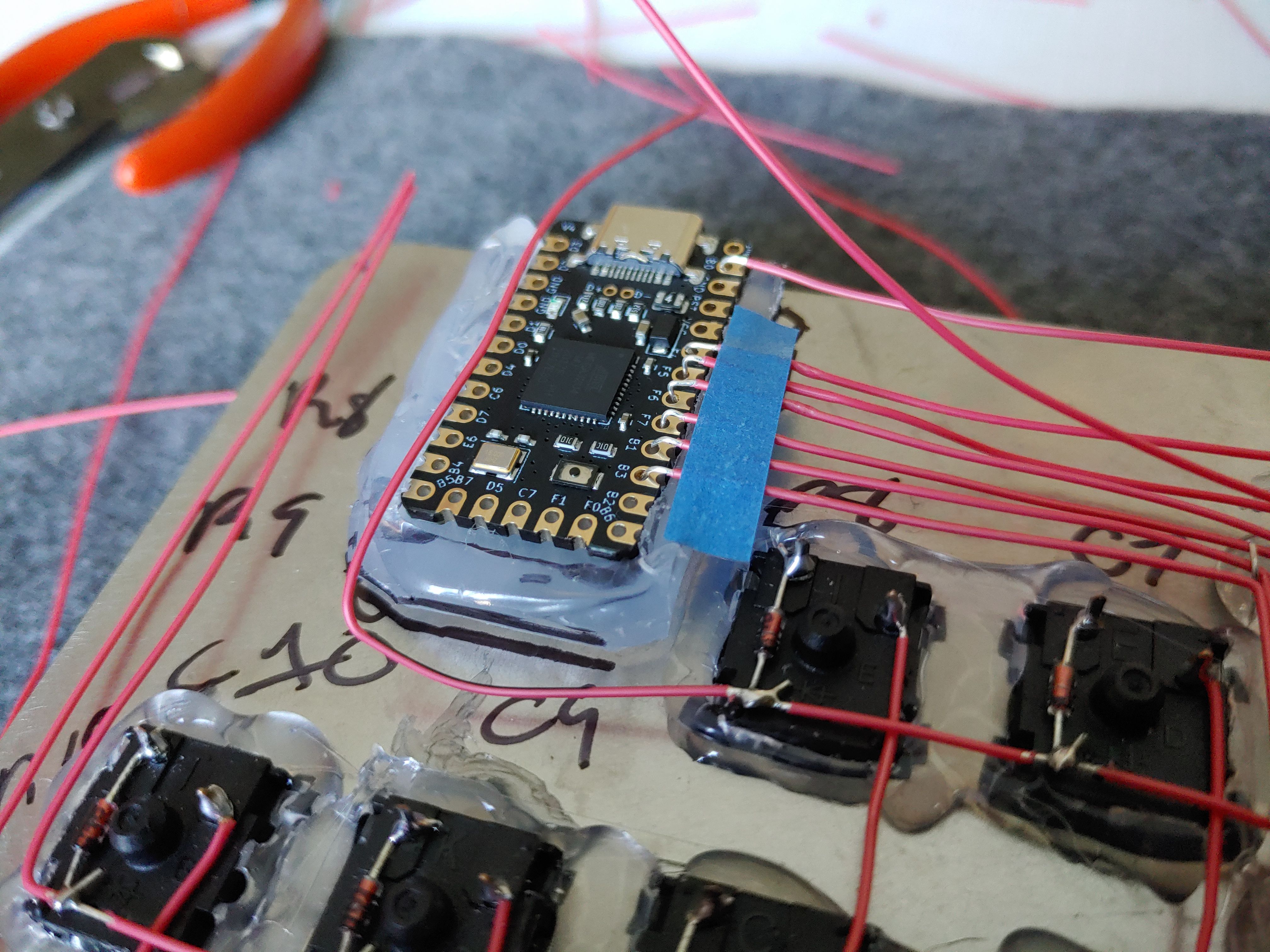
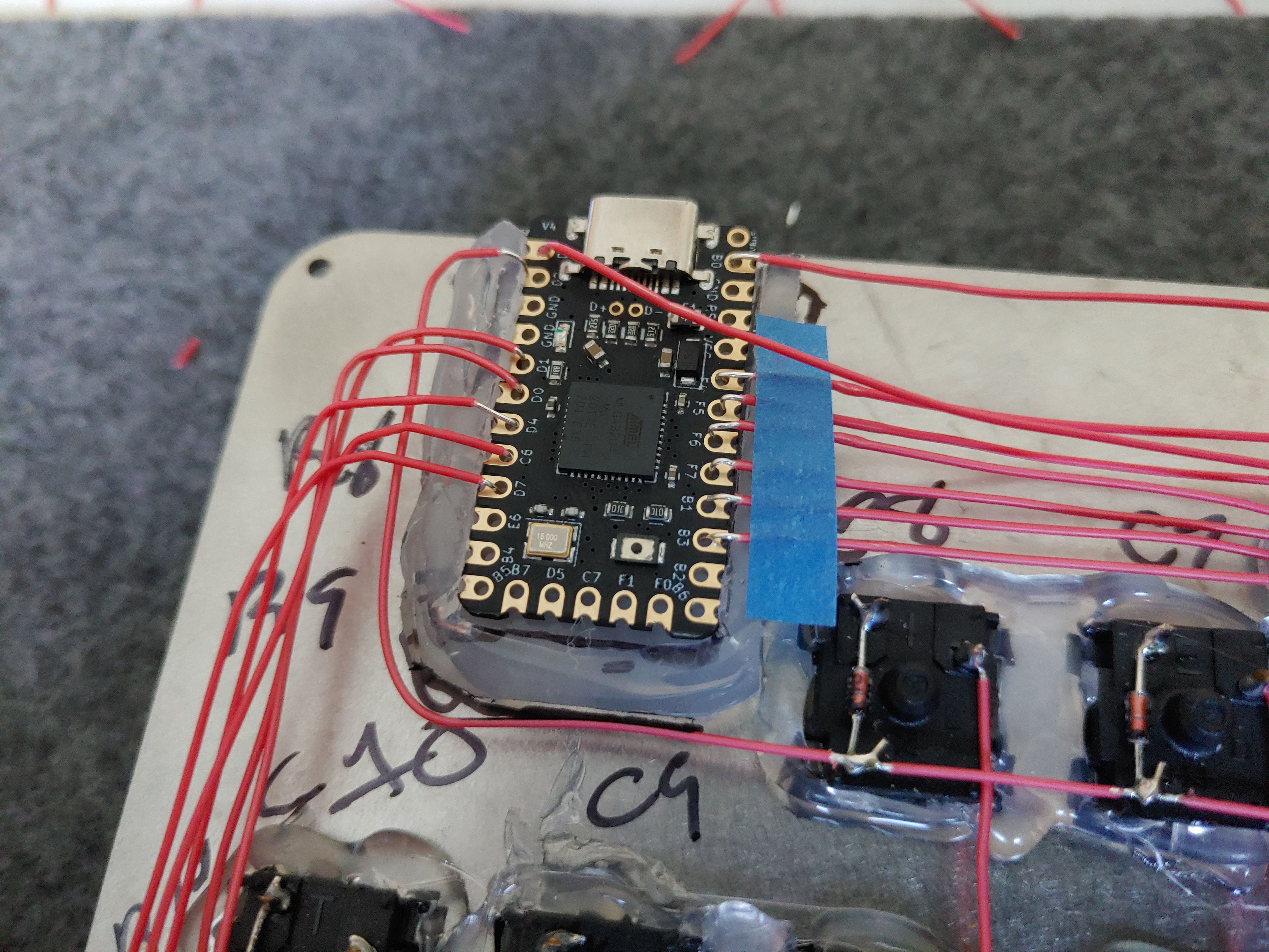

I had been trying to keep the wires nice and pretty up to this point, but some of these final linkages just required inconvenient wire paths. R7 had to get over and across the controller, and C1-C6 had to come down at an angle. Oh well.
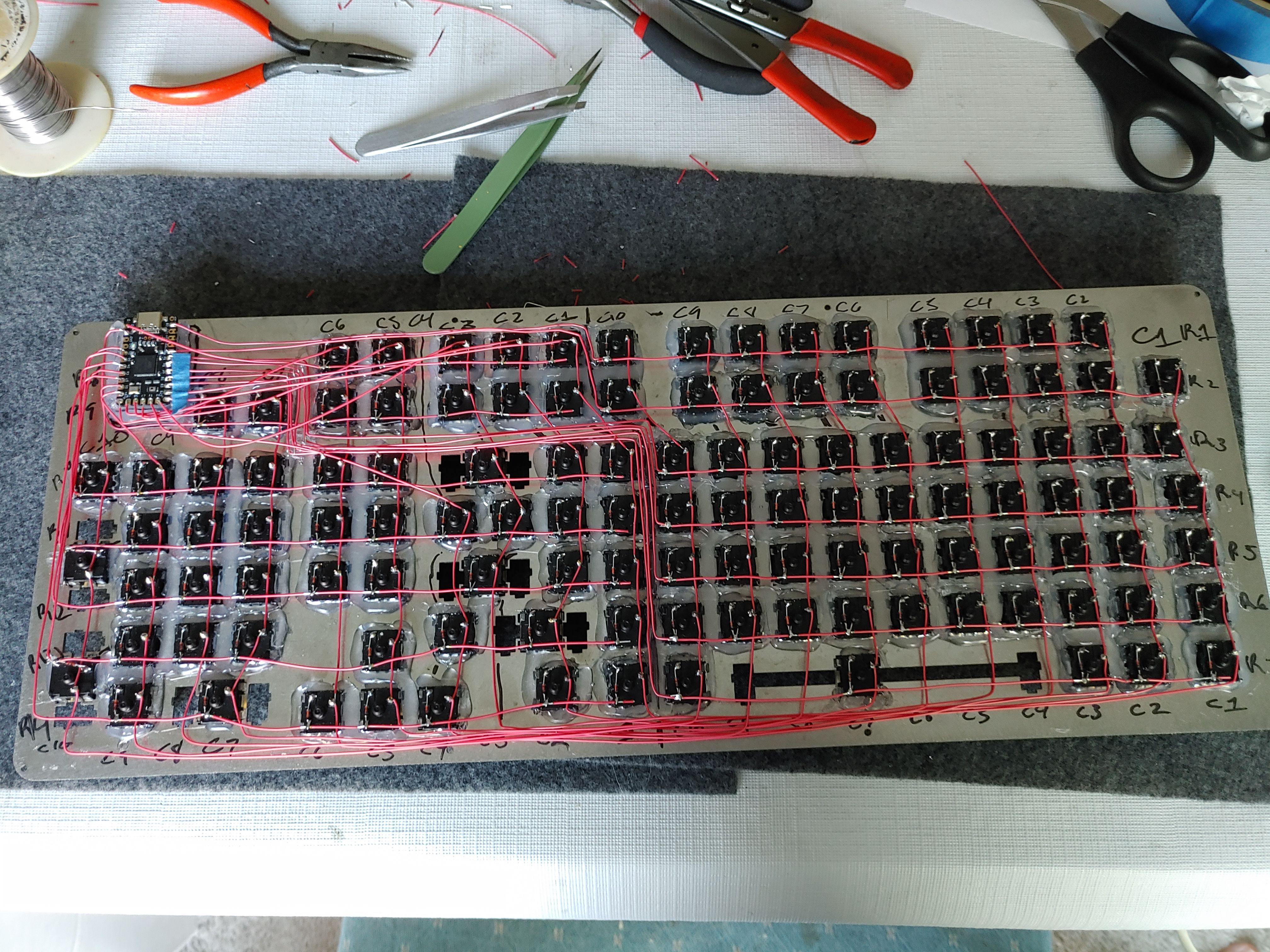
It works! I made some firmware changes to accommodate the change I made during wiring, and also fixed some keycodes that I had chosen incorrectly (the `/~ key should be KC_GRAVE, because KC_TILDE always types ~ even without shift, etc.)
The base (§)
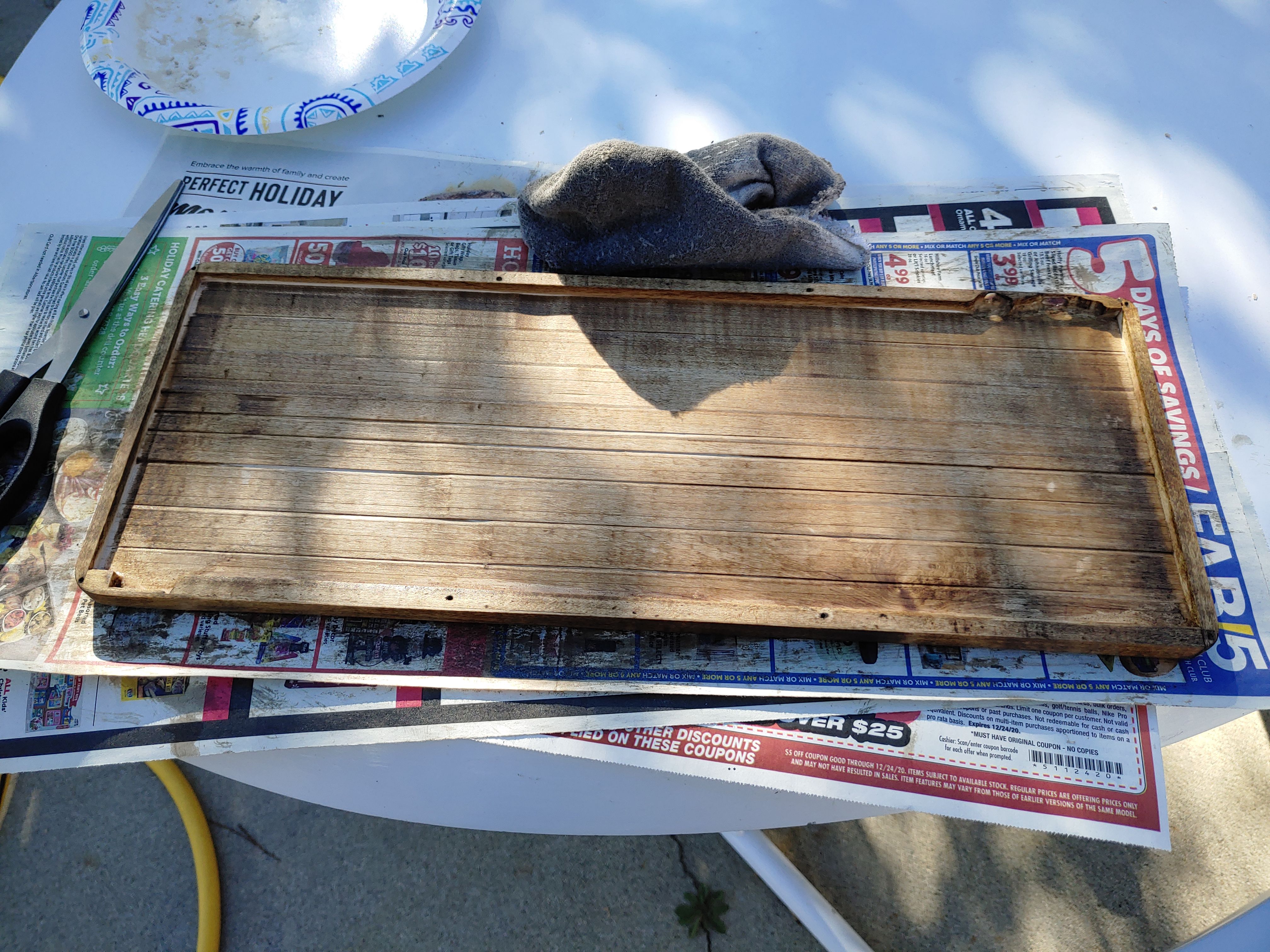
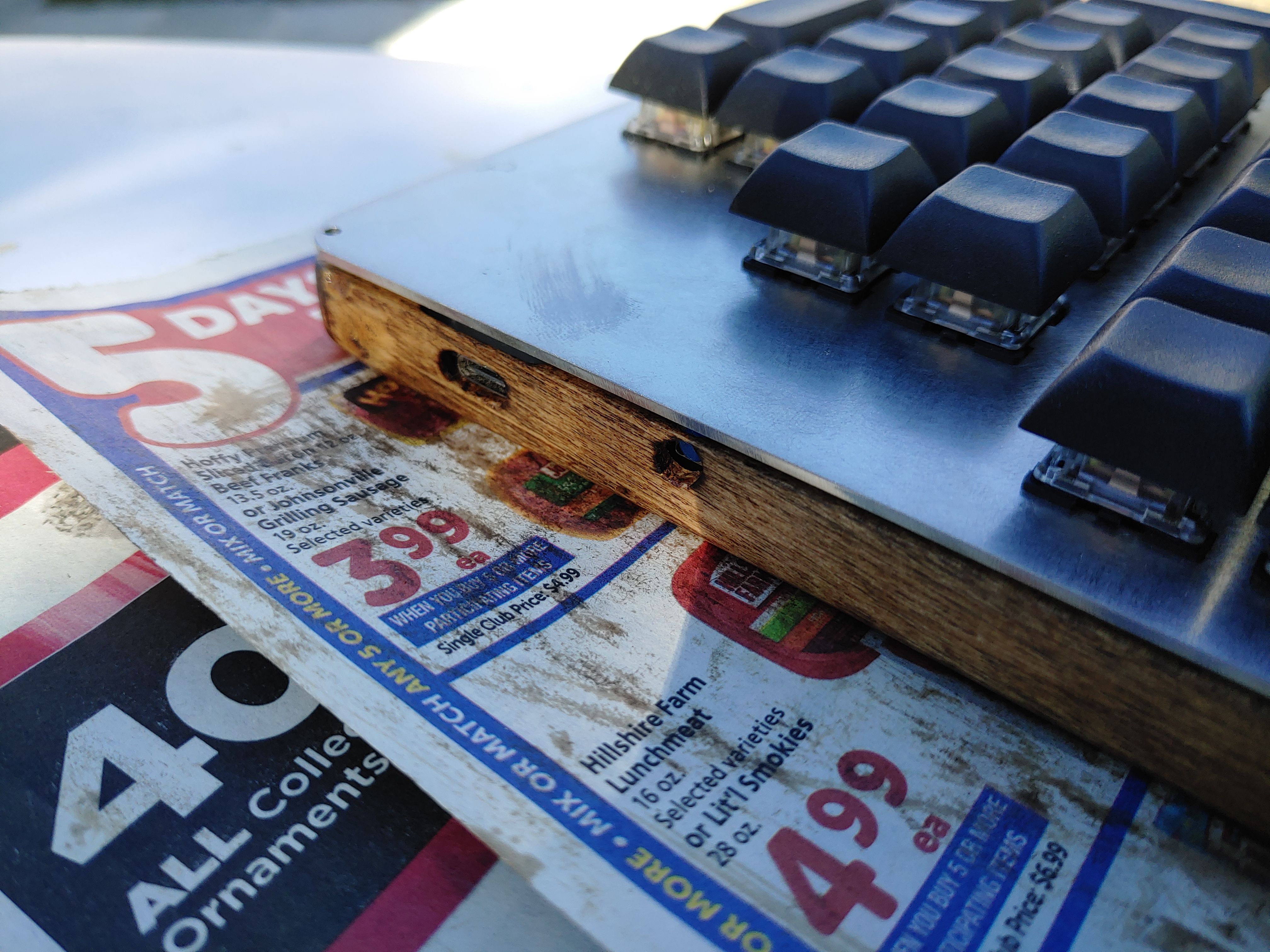
I wanted to make the base out of a dark piece of wood, or at least wood stained dark. My grandfather has a workshop, and in fact he's the one who built my desk, so I went over to his house and we put something together.

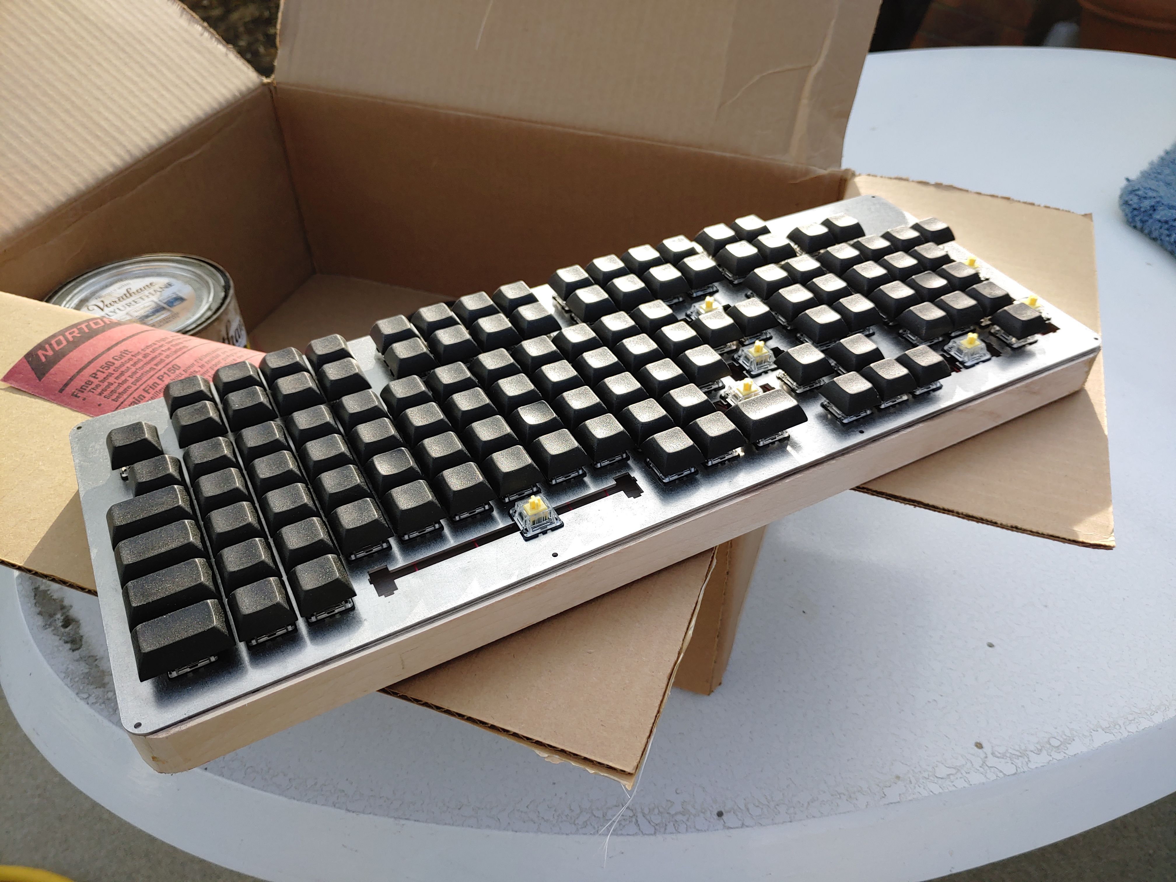

On my own time, I brought the height of the base down, drilled the screw holes, and added a hardware reset button to facilitate easier experimentation with the firmware. The plug and reset button holes required a couple rounds of adjustment, and as a result don't look very good, but I'll consider it a learning experience. The piece of wood which goes over the plug hole is dangerously thin as it is, so I can't experiment with the shape any more. There's nothing stopping me from unscrewing the plate and making a whole new base if I choose to. Except for the fact that this one was made with my grandfather and will someday be a family heirloom.
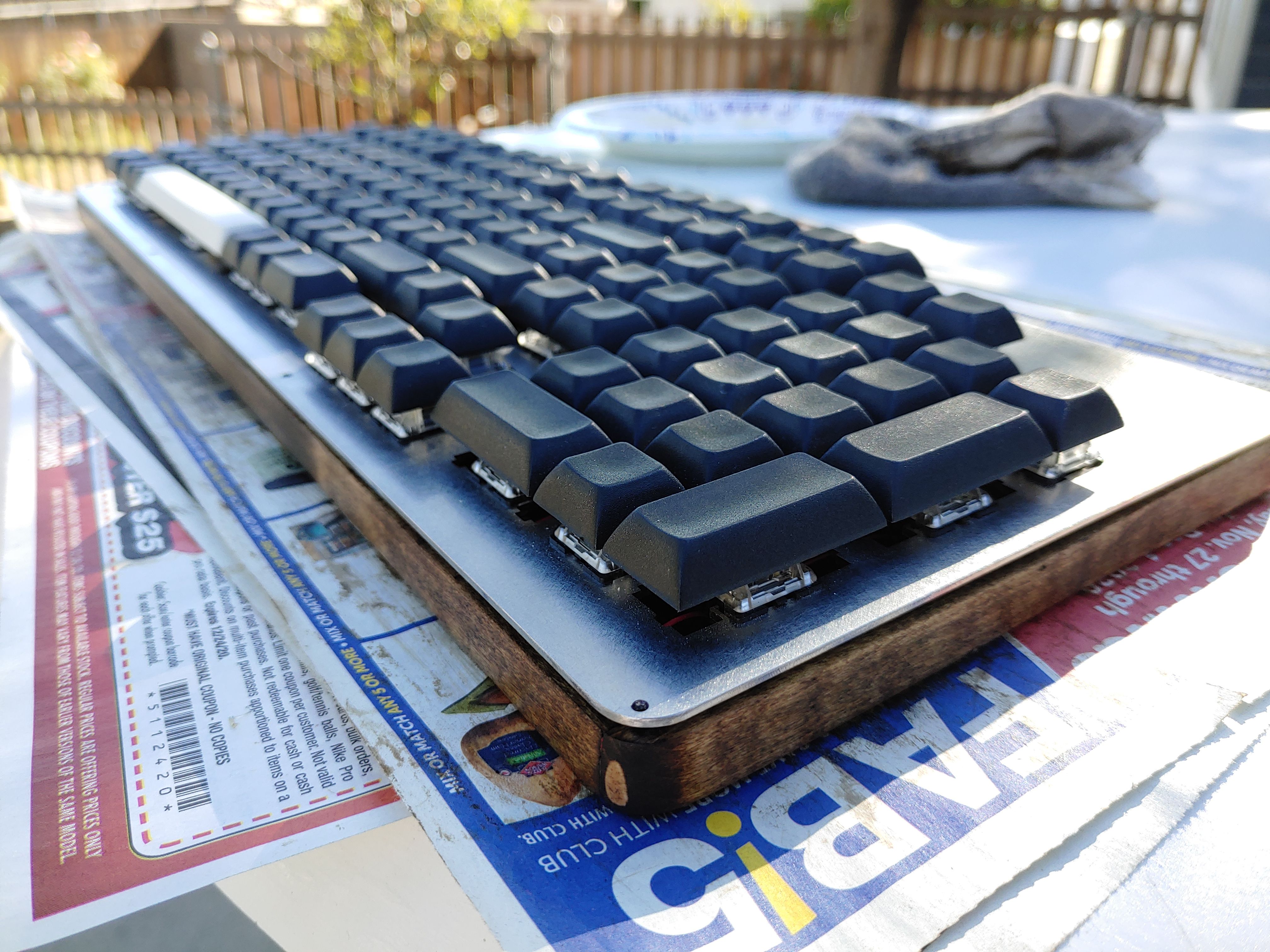
Then I did the stain and other finishing touches, and screwed the plate down.

Stabilizers (§)
This section shouldn't be last, but it is.
My keyboard uses a 6u space, which is uncommon. The standard size is 6.25, which of course would not fit in the ortholinear design. There are fewer vendors selling 6u space stabilizers, and they are all in China / Taiwan. I found a set on ebay, ordered them, and waited. And waited. And waited. UPS had lost them, and they simply never arrived.
After a month of waiting, that's when I put the rest of the keyboard together and figured I'd put the stabs in if they ever arrived. My family asked me "did you get a refund from the company?", and I just said "it's not really a company, it's just some dude in Taiwan, and it was UPS's fault...". I felt bad losing the money, but would also have felt bad taking the money back in case UPS eventually found it and sent it over. I should have been less timid, but oh well.
For six months, I used the Nearer with a 1.5u key as my spacebar and no stabs under Shift, Enter, etc. It worked perfectly fine, and I adapted very well to a 1.5u space, but it was embarrassing to look at and I knew I couldn't publish this article without proper stabs. So I ordered another set on ebay and they arrived about two weeks later.
With a 6.25u space.
I argued with the vendor over the course of nine!! emails that a 6u stab should be 95mm instead of 100mm, and he eventually sent a replacement.
On my previous, rubber dome keyboard, the stabilizer bars were fully accessible after simply removing the keycaps, so it didn't occur to me that Cherry stabilizers actually go underneath the plate, and are supposed to be installed before the switches are in place. But, I was able to add them retroactively, which I described in a video. This required cutting away some of my beautiful hot glue with a craft knife to make way for the bar.
Conclusion (§)
Price breakdown (§)
If I had known these numbers before starting, I probably would have put the project off yet longer. But my technique of getting started before planning everything so I couldn't back down worked great.
Prices are expressed as $item+fees in USD, since shipping / tax will be different everywhere.
| item | price |
|---|---|
| 140×Gateron Yellow | $29+18 |
| 129×keycaps | $40+9 |
| 150×1N4148 diodes | $12+1 |
| Switchplate | $60+20 |
| 6u + 7×2u Stabilizers | $16+4 |
| Elite-C controller | $18+5 |
| USB-A to -C cable | $6 |
| Odds and ends (hot glue) | a bit |
Coming in at around or just under $250.
And it would be wrong of me to ignore the benefit of materials I already had or borrowed from my family: Soldering iron, wire, hot glue gun, wood & woodworking tools, wood stain, sandpaper.
My mom kept asking me "are you going to make and sell these?", but with $250 material cost and at least 24 hours of labor, I don't think I'd find many takers.
What I'd do differently (§)
- Bring screw holes farther from the edge of the plate.
- Add more screw holes to deal with non-flat plate.
- Improve accuracy of base shape to fit more flush with the edges of the plate.
- Improve accuracy of drilled screw holes in the base, as some of the screws are not totally plumb.
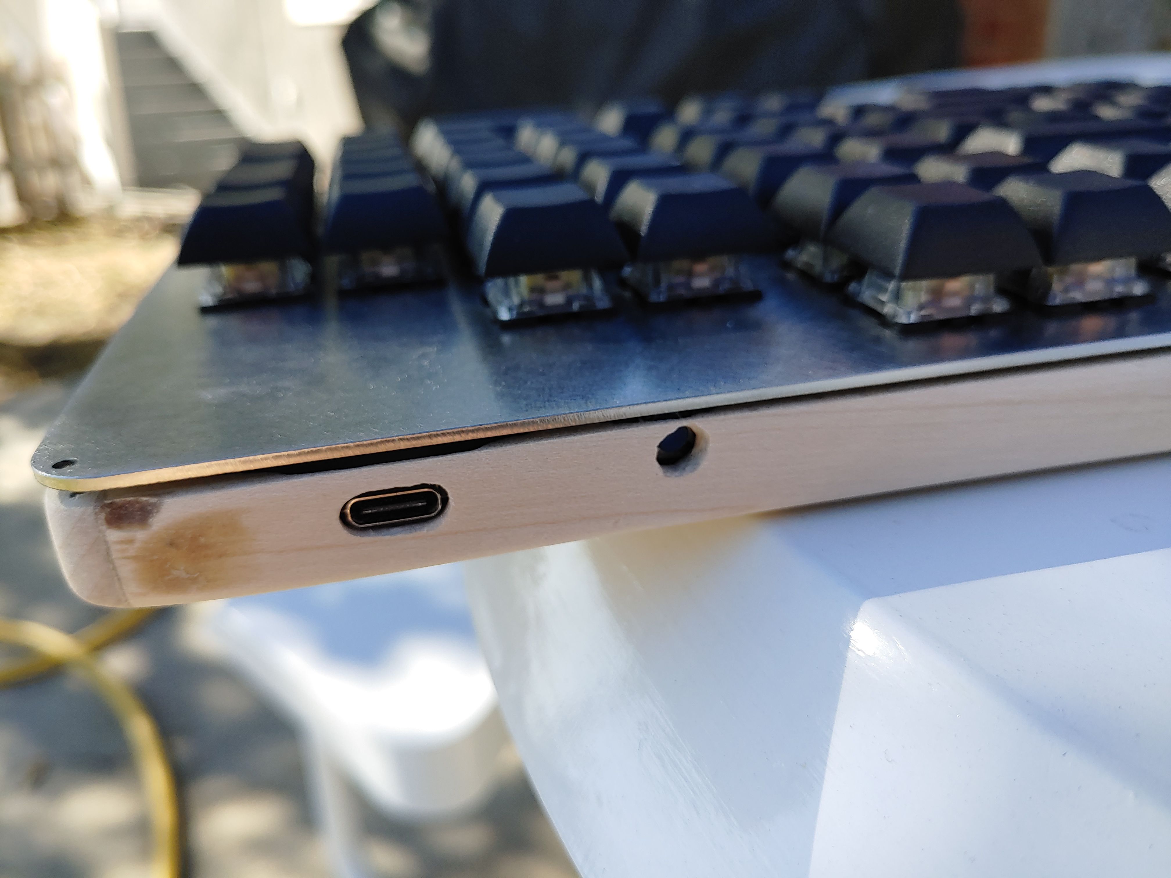
- Improve shape of USB and reset button holes.
- Use something other than hot glue. I do want to protect against switches coming out of the plate, but hot glue actually doesn't adhere that well to the metal. My firmware reset button has come loose, and I taped a piece of felt to the inside of the case to give it a friction fit so I can still push it securely.
Overall, I am satisfied. Typing on the Nearer feels cool, and I'm glad to have a unique piece of equipment that I put together myself.
Thank you for reading.
- Replace github links with git.voussoir.net.
- Replace demo video with a new 4k60 version.
- Fix typo "spantaneous", improve diode explanation.
- Remove excessive and repetitive glamour shots.
- Add tag electronics.
- Replace youtube links with embeds.
- Fix typo "over to the controller".
- Add kb_nearer.md.
If you would like to subscribe for more, add this to your RSS reader: https://voussoir.net/writing/writing.atom